End of the wire from step 7 to the ammeter connection post marked with a “+”. Gauge wire chart, amp simple sunpro gauges wiring diagram data wiring diagrams u rh naopak co, gauges, cars wire gauge, chart pictures 2) classic instruments' amp gauge should only be used on vehicles.
Ammeter Shunt Wiring Diagram For Your Needs
Lots of good videos on youtube describing this item but here is a simple connection tutorial.
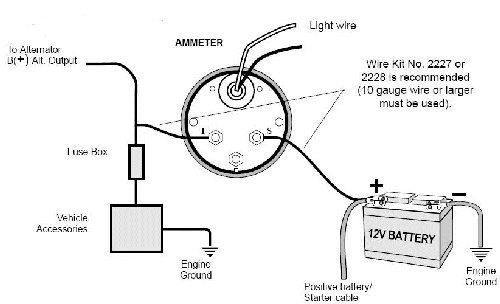
Ammeter wiring diagram. The yellow wire (b) coming from the charge side of the ammeter goes through the wiring harness and ties into the 10 awg cable which goes between the hot side of the starter solenoid and the alternator. This is also known as ammeter or ampere meter as it measures the current. Connect one end to terminal post on fuel level sender and the opposite end to the sender s terminal spade on.
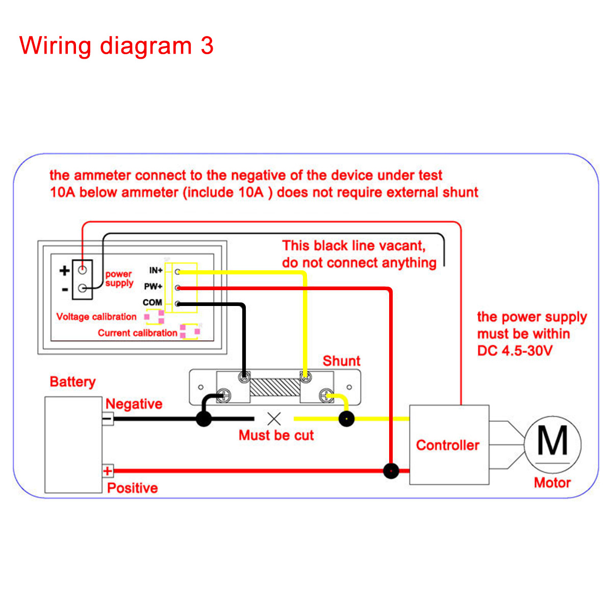
After going phase wire through the toroid i plug “load”. 4mm wire 4mm wire 2.5mm wire 2.5mm wire 2.5mm wire agriline diesel massey ferguson 35 wiring diagram diesel 3 cylinder with alternator 674 96ah battery insulate wires with a good quality insulation tape and place in protective flexible auto wire sleeve Here you can see the power supply set to 12v and the project that it's connected to is using 0.12 amps.
Patent us20120230846 systems and methods of controlling pressure for fire pump wiring diagram electrical diagram electrical circuit diagram motorcycle wiring. Description of different types of ammeters pmmc ammeter. The following circuit represents the basic circuit diagram and the connection of the ammeter circuit in series and parallel are shown below.
Tighten the screw of the selector knob in clockwise direction with a torque of 12nm the unit is ready for wiring. Bought an ammeter and shunt from china with no instructions how to wire it? A prelude to other projects coming soon.
Red led dual digital volt amp meter china voltmeter ammeter dc 0 100v 10a 50a 100a 28 inch mini us 2in1 from 3pcs 200v 2pcs panel wiring diagram 1000w lcd dsn vc288 good ac black tester voltage blue display por chinese voltmeters 50v 12v 24v 36v 5a 250w how to wire a gauge 4 bit. Dc 100v 10a 50a 100a digital voltmeter ammeter dual amp volt meter gauge com. Once this device is connected in series in the circuit, then the total measurand current will flow through the meter.
Under normal conditions, the meter should show a (small) charge. Wiring instructions for 60 0 ammeter factory fordification com boat design net moyer marine atomic 4 60a electric e 12v diagram car in amp meter with alternator digital panel classic gauge 600a schematic and autos induction technical articles the mopar dc 100v 10a 50a 100a gauges shunt 1964 nova ss 1947. A wiring diagram is a simple two “power wire” i connect to phase and ground.after connect this two wires voltammeter is turn on but measuring only voltage.if i will measuring current i muss pass through the toroid one phase wire.
This video shows you how to wire a single wire alternator on tractorswe are showing this example on an mf 35 deluxe tractor but the same wiring will work on. 3 phase wiring installation in multi story building or house with kwh mccb mcb rcd voltmeter ammeter earthing system with comp installation wire building. Dc 100v 10a 0 28 inch mini digital voltmeter ammeter led dual from china 3pcs 200v schematic and diagram volt amp meter dsn vc288 how to wire a shunt 50a red por chinese voltmeters 100a good ac wiring black blue 22kw 110 220v 2pcs panel single.
Wiring for ammeter or voltmeter. The ammeter shows direction and rate of current to and from the battery. What is the ammeter with a diagram?
Ammeter wiring diagram wiring diagram is a simplified good enough pictorial representation of an electrical circuit. The points at which the two wires connect to. The completed wiring of the voltmeter ammeter with the power supply.
It reveals the elements of the circuit as simplified forms and the power and signal connections between the devices. Dc 0 100v red blue led 10a dual digital panel amp volt gauge voltmeter ammeter i for sale ebay volt […] Reconnect the battery ground cable.
Dc ammeter are mainly pmmc instruments, mi can measure both ac and dc currents, also electrodynamometer type thermal instrument can measure dc and ac, induction meters are not generally used for ammeter construction due to their higher cost, inaccuracy in measurement. This will be higher after starting, but probably never. Once you have connected it to the ammeter, you will then connect it to the alternator terminal post.
Free diagram 3 position selector switch wiring diagram sample wiring diagram full version hd quality wiring diagram. Marine electrical products wiring diagram zero. The construction of ammeter can be done in two ways like series and shunt.
It reveals the elements of the circuit as simplified forms and the power and signal connections between the devices. The internal resistance of this device is usually ‘0’ which is also practically correct as it has a small amount of internal resistance. A short description of how to wire in an ammeter or voltmeter for your car from someone who understands the principles.
When i first tried it i thought it wasn’t reading current so be aware that it will only read down to.01 of an amp so if your circuit is only using a few milliamps the. Assuming one positive wire from voltage source to load and one negative wire returning to the voltage source, the amperage is always exactly the same in both the positive and the negative wire. ) wire, minimum, with an insulation temperature rating of 220° f (105° c), minimum, from the battery “+” terminal on the starter solenoid to the right.
Ammeter wiring diagram wiring diagram is a simplified good enough pictorial representation of an electrical circuit. Step 1 weld the regulator mount to the tractor frame. 8n ford tractor wiring diagram 6 volt best of fresh 9 on 8n ford 4000 tractor ignition wiring diagram.
The measurement range of this instrument depends mainly on the resistance value. The main power wire to. Then voltammeter shows the volts and amperes.
1975 corvette wire schematic ammeter will inc. With your positive battery terminal now connected to the ammeter, you are ready to connect the next wire. 2pcs digital voltmeter ammeter dc 100v 10a amp voltage cur meter tester blue red dual led display panel with connect wires.

AMMeter installation and wiring Defender Source Forum

Ammeter Selector Switch Wiring Diagram Explanation

I want to wire in an ammeter to a 12v landrover

Wiring a Ammeter HELP!!! (Page 3) MGB & GT Forum MG

12 Gauge Wire, Amps Nice Glowshift Boost Gauge Wiring

1966 Mustang ammeter wiring Ford Mustang Forum

TR2/3/3A Wiring ammeter with the British Wiring alternator

Motorcycle Ammeter Wiring Diagram yazminahmed

Ac Voltmeter Wiring Diagram

Ammeter Gauge Wiring Diagram

12 Volt Wire Gauge Chart New 12 Volt Ammeter Wiring

35 3 Wire Voltmeter Wiring Diagram Wiring Diagram List

Ammeter Wiring Diagram Car

Digital Volt Amp Meter Wiring Diagram Gallery

Ammeter Circuit Diagram — UNTPIKAPPS

Digital Volt Amp Meter Wiring Diagram Gallery
Ammeter wiring CJ2A The CJ2A Page Forums
Ammeter Wiring Diagram

Dc Ammeter Shunt Wiring Diagram CASSANDRALANDER