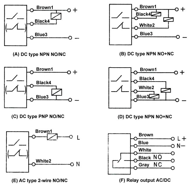
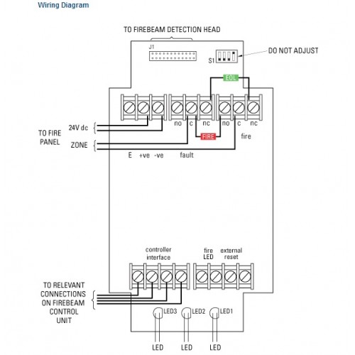
Utilising reflective detection technology, the detector is formed by two parts: Wiring distribution diagram (wiring diagram) names and functions of optical axis adjustment parts optical axis adjustment using the alignment mechanism
System Sensor BEAM1224, BEAM1224S User Manual Page 5 / 13
15 19 14 3 20 2 11 2 6 alarm signal 1 aux.
Beam detector wiring diagram. Reference to the wiring diagram figure 2 & figure 3 ensure that the field wiring is terminated into the dual gang installation box. Application guide for projected beam smoke detectors available on request that the system is undergoing maintenance and will be temporarily out of. Eaton's beam detector provides excellent smoke detection compared to standard optical detectors in large, open areas such as warehouses, factories, arenas and airports.
For us installations it is typically a short circuit. This is the basic fire alarm system used in household wiring. Wiring diagram for connection of a single conventional detector to a zone:
The fire beam brochure contains detailed information on the range of fire beam products. Test station) for wiring diagram. System sensor model is a long range projected beam.
Parts diagram (not to scale): Beam is a conventional device, below are suggested wiring configurations for single and multi heads on a zone. Diagram to avoic interference between beams.
The wiring diagram to connect the r(s) to the key. The units detect intruders only when both upper and lower beams are simultaneously interrupted, preventing nuisance alarms due to fallen leaves, etc. Projected beam smoke detector 3825 ohio avenue, st.
Coverage of light beams upper detection line lower detection line transmitter receiver keeps birds and small animals away from the sensor, helping to reduce false alarms. A smoke or heat detector can be installed to the existing or new home wiring. A surface that moves, shifts, vibrates, or warps over time may cause false alarm or fault conditions.
When the beams detect the presence of a moving object, the detection will cause the gate(s) to stop and reverse to the fully open position. The installed onto standard two gang electrical box, or directly by drilling the holes and fixing with plugs. Installation wire used for the beam detector shall be no.
10 beam detector wiring diagram. Projected beam smoke detector 3825 ohio avenue, st. The system is designed to be mounted so the beam will project between 19” (0.5m) and 24” (0.6m) below and parallel to the ceiling.
Specifications are subject to change without notice. Parts diagram (not to scale): The gto/pro photoelectric dual beam detector uses dual beam and through beam technology to reduce false detections when detecting obstructions.
As long as the beam is obstructed the gate(s) will remain open. For general information, refer to the application guide for projected beam smoke detectors available on request from your supplier. Initial selection of a proper mounting surface will eliminate nuisance alarms and fault signals.
In our basic wiring diagram, a single or multiple heat and smoke detectors are installed in the home by connecting the live (line or hot), neutral, ground and an interconnected wire to the alarm. The beamsmk allows system sensor reflected beam detectors to be mounted when surface wiring is used. The beamsmk allows system sensor reflected beam detectors to be mounted when surface wiring is used.
Diagram illustrates correct placement of photo beams in relation to the gate. The fire beam plus brochure download. It is particularly suitable for protection of premises where smoke appearance is expected in the first phase.
In the event of fire the smoke generated will. The addressable beam detector is compatible with simplex 4100es and 4010es fire alarm control panels. Fire alarm wiring diagram new wiring diagram manual call point valid in 2021 fire alarm system fire alarm fire protection system.
It's a great introduction to the fire beam all inside one pdf document. Wiring and connection connect the wires to the required terminal (9.144m) on either side of the beam, providing a maximum.
Beam detectors require a very stable mounting surface for proper operation. Lateral detection may be up to 30ft. Mount the detector on a stable mounting surface such as brick,
It explains how it works, the features you get as standard, as well as information about our kits and accessories. The nr40tx and nr80tx are beam detectors designed to provide an alarm relay activation upon detection of an intruder moving through a pair of invisible pulsed infrared beams. 147 pages beam detector installation manual.
Mounting position beam detectors require a very stable mounting surface for proper Thefirebeam can easily be made addressable with the use of a manufacturers interface and in some cases can also be powered from the loop, ie with the apollo xp95 switch monitor with isolator. The receiver is constantly monitoring and measuring the intensity of the beam transmitted by the emitter.

Extronic Elektronik AB 14A. Wiring diagram for loading

Through Beam Photoelectric Sensor Wiring Diagram Download

The science behind optical beam detection in large, open

Arindam Bhadra Fire Safety Beam Detectors Installation

Through Beam Photoelectric Sensor Wiring Diagram Download

Beam Sensor Wiring Diagram New Images Beam

Long Range (10mt) IR Beam Break Detector Detector
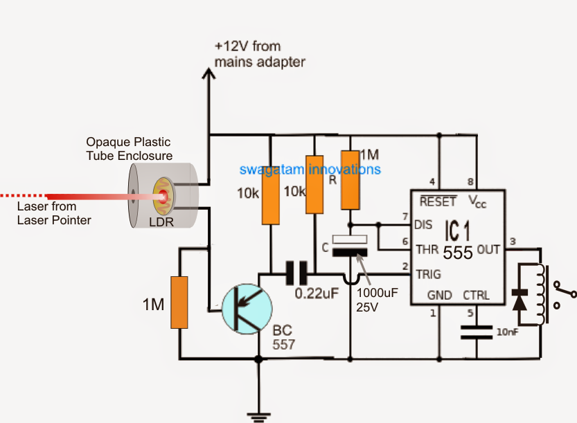
infrared IR proximity detector/ IR beam barrier circuit

Collection Of Through Beam Photoelectric Sensor Wiring

Through Beam Photoelectric Sensor Wiring Diagram Download

Through Beam Photoelectric Sensor Wiring Diagram Download

Wiring Smoke Alarm Diagram Wiring Diagram Schemas
Đầu báo khói SPC24 Hochiki Beam Smoke Detector
Photoelectric beam detectors for access control system and
Beambreak Detector For Camera Shutter or Flash Control
Extronic Elektronik AB 14B. Facade lighting for buildings
