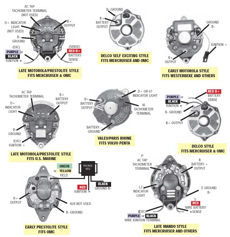
Make sure you wire your marine alternator. If you go to volvo penta's site you can have a look at the aq130 user's manual, where the wiring diagram is there.

Marine Alternator 3 Wire Diagram Wiring Diagram
Wiring diagram arrives with several easy to stick to wiring diagram directions.

Boat alternator wiring diagram. To start the engine you need a+ feed from the battery to the + side of the coil[this acts as an ignition live,to be disconnected when not testing the engine ]next you need a heavy + feed directly from the starter to the battery[use good heavy cable]also a good heavy earth lead from the battery negative to the engine block[jump leads work great]connect the distributor. When you make use of your finger or perhaps the actual circuit with your eyes, it is easy to mistrace the circuit. 1 trick that we 2 to printing a similar wiring plan off twice.
This is the aq130c manual. Print the wiring diagram off plus use highlighters to trace the signal. Ocean ecosystem food chain diagram.
3 position switch wiring diagram. This wiring configuration will excite the alternator to start charging when the engine is running at low rpm’s. Many alternators require ignition voltage to initiate charging.
By tom burden last updated 6 1 2020. A view of the connection end of the alternator can be seen in this picture. This voltage is provided by the indicator lamp on most vehicles.
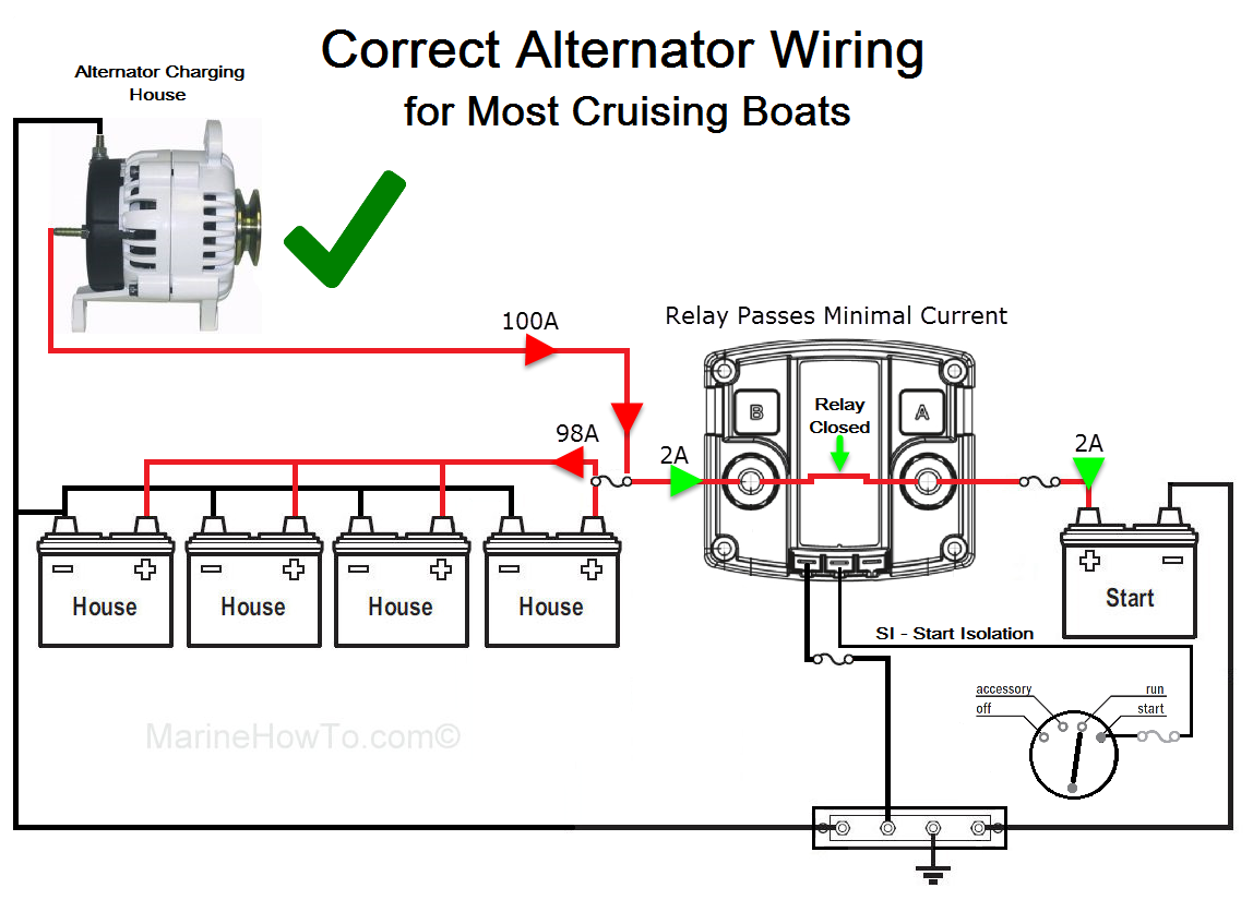
The following basic wiring diagrams show how batteries battery switches and automatic charging relays are wired together from a simple single battery single engine configuration to a two engine one generator and four battery bank system. Charge wire connects from the alternator to the battery through the. **full parts list below:***amazon electric section:
Terminal 1 must receive voltage. You need to draw out a wiring diagram and id the alternator. The other two show hei ignition w/1 wire and 3 wire alternators.
This is what excites the field of the alternator. Connect the red wire to the alternator case and touch the black wire to each of the large terminals in turn. Download mando alternator wiring diagram free pdf, download mando alternator wiring.
However both these leads to. Two of them show points ignition w/1 wire and 3 wire alternators. The ig or r contact is a switched wire from the ignition switch.
Once id'ed, lots of info on gm alternators on the web. Here are 4 different engine harness diagrams, complete with wire gauge and colors. Volvo penta aq130 alternator wiring diagram.
The resistor or directly to the key switch itself (switched side). It’s supposed to assist all the typical user in developing a suitable method. Although the regulator fitted to mine is a 12v one.
Most can be converted to single wire. If both large terminals give a buzz or a similar reading (not the i for infinity) both are output terminals, otherwise you can only use the one. The wire supplies voltage directly to the alternator regulator so that it always receives voltage to switch on.
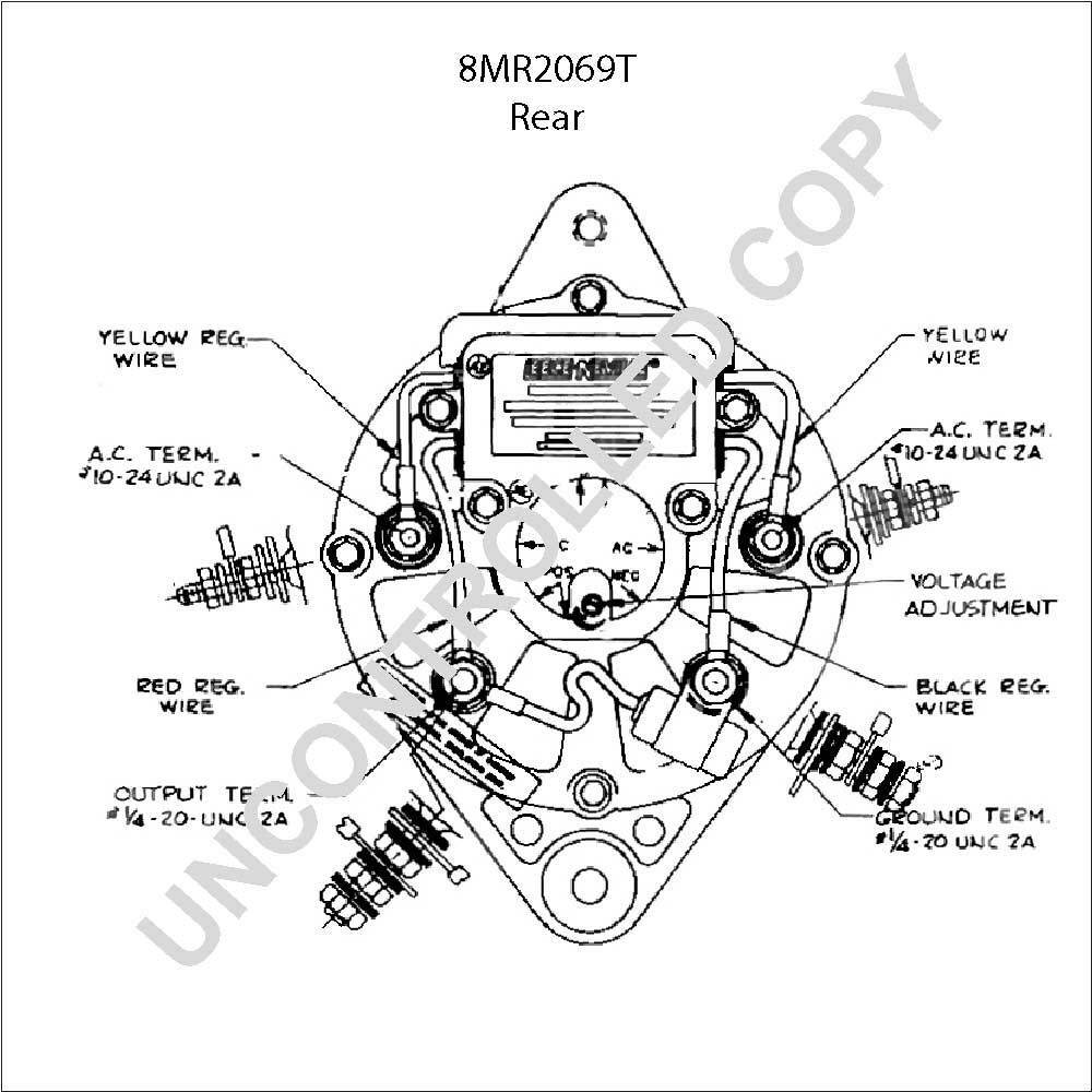
Diagram alternator 8mrf 8mrf 8mrf 8mrf 8emfa 8mrfa 8mrf 8emf motorola, mando, delco 10 si series replaces majority 12 volt motorola, sev,. Terminal) then there are 2 side terminal wires and directions state: An output voltage and current goes from the alternator to the battery.
If you're using an aftermarket ignition such as an msd, be sure and follow their instructions for wiring the box to the distributor. Ok, here is a basic wiring diagram: Boat motorola alternator 8mr2011f wiring diagram.
Many people change alternators from stock. Make a rough drawing of the boat looking down from the top. The other terminal is the exciter.
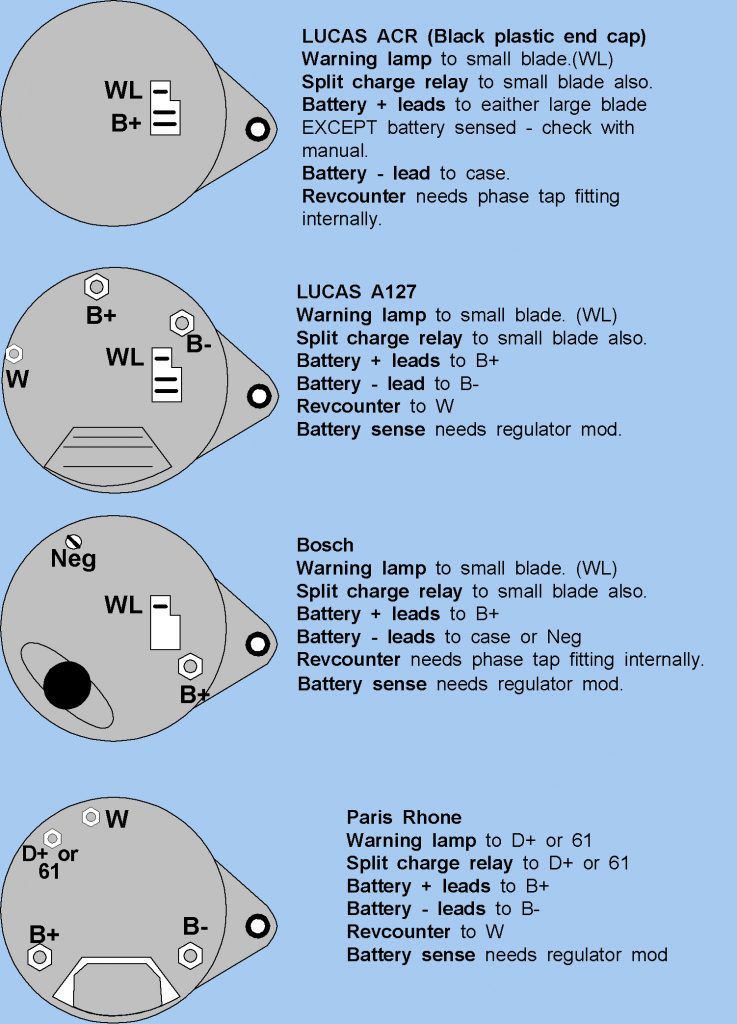
Otherwise, the structure won’t function as it should be. Plano concave lens ray diagram. Below you will find the most common alternator circuits used on marine applications.
The wiring schematic in attached picture is a different alternator, but looks identical. Using your schematic, put in where the equipment, fuse boxes, buss bars, switch boxes and wiring are going to go. Some pics of common gm alternators.
Code b+, a or 30: Each part ought to be set and connected with different parts in particular manner. This prestolite drawing indicates the free wire leaving the regulator is the excitation lead, which i would have thought meant it connecting to the wire from the warning light.
You must verify that all required connections are connected to the proper terminal and have the correct voltage in order for the alternator to operate properly. This is what designers call a general arrangement and shows how the boat is laid out. That s terminal the ignition wire.
Basic wiring diagram to , replace the alternator and the exciter wire pigtail. 2 1/2 year restoration project after all you need to do is put the rebuilt engine back in. These guidelines will likely be easy to grasp and apply.
Make a drawing showing where the wiring will be.

Alternator Charge Wire Boat Wiring Diagram Wiring Forums

[DIAGRAM] Prestolite Alternator Wiring Diagram Marine
Mando Marine Alternator Wiring Diagram
wiring my new alternator Shamrock Boat Owners' Club
Marine Alternator Wiring Diagram M59819

Alternator Charge Wire Boat Wiring Diagram Wiring Forums

Volvo Penta Alternator Wiring Diagram yate Pinterest

Alternator Wiring Diagram Boat Wiring Diagram Networks

Find Out Here Prestolite Alternator Wiring Diagram Marine
Alternator Wiring Diagram Boat

How to properly wire your Marine Alternator

Fine Motorola Marine Alternator Wiring Diagram Photo

Alternator Charge Wire Boat Wiring Diagram Wiring Forums

Delco Remy Alternator Wiring Diagram Marine Tachometer

Trying to find wiring diagram for alternator. not sure

Boat Dual Battery Wiring Diagram For Yanmar Sel Wiring

Marine Alternator Wiring Diagram Manual 7
Marine Alternator Wiring Diagram

Marine Alternator Wiring Diagram Inspiration Delco Of 2

