Ad source code goose and opc interfaces from sisco for power system communications. The wiring diagram for a.

Catalog Number Ex9C800E22MG, Ex9C Series 220 Volt (V
4 table 2 nema and iec terminal markings.

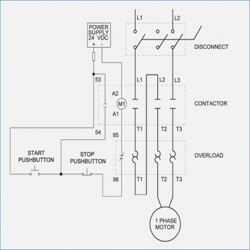
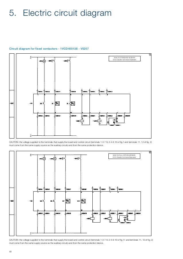
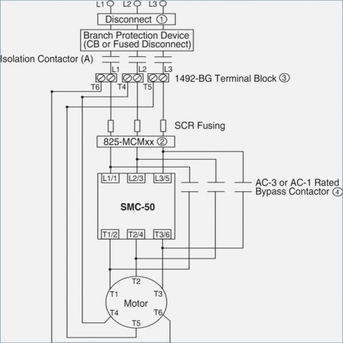
Iec contactor wiring diagram. Contactor breakers limit switch no static control standard elementary diagram symbols. Variety of definite purpose contactor wiring diagram. Lighting contactor wiring diagram with photocell elegant cool v wiring diagram contemporary electrical and wiring uploaded by alena on thursday september 14th in category wire diagram.
Thus c1 contactor is also energized and three phase supply will reach to the motor. Green and red or start and stop buttons. Hi, i have some questions regarding how contactors and relays are numbered (tagged, identified) in wiring diagrams.
Drain cycle, tank empty electric alternators: 3 set pilot device a contacts to. Iec contactor wiring diagram bureaucraticallyfo.
Iec 60947 3 wiring diagram wiring diagram is a simplified welcome pictorial representation of an electrical circuitit shows the components of the circuit as simplified shapes and. Electrical diagrams on with contactor esquemas connect your euro din type timer to loads much higher than the rated load of the timer by choosing the right amperage of contactor & mcb. Fill cycle, tank full fig.
The diagram symbols in table 1 are used by square d and where applicable conform to nema national electrical manufacturers a ssociation. Contactors are used to provide this isolation. For more information on lighting, definite purpose (dp), and elevator ratings for tesys d and tesys f contactors, refer to catalog 8502ct9901.
Iec contactor wiring diagram bureaucraticallyfo. Otherwise the arrangement wont function as it. You will be in a position to understand exactly once the assignments ought to be completed, that makes it much simpler to suit your needs to correctly manage your time and.
Basics 9 416 kv pump schematic. It didn t come with any documentation and the website does not. All products are available as open devices or as an enclosed ac starter package.
Wiring diagrams.a34 springer controls carries a complete line of iec contactors and relays up through 800 amp and 500 hp. Iec contactor wiring diagram bureaucraticallyfo. 2 wiring diagram elementary diagram output selection of both sensors in minimum (n.o.
Refer to the motor manufacturers data on the motor for wiring diagrams on standard frame ex e ex d etc. Use these tips to learn how to wire a contactor. Class 9039 type x fig.
Ups 230vac + critical loads non critical loads Contactors use 120 volt standard power to energize a magnetic coil, which causes a set of internal contacts to close and provide higher power to the equipment. Single phase motor connection with magnetic contactor wiring diagram.
Wiring diagram book a1 15 b1 b2 16 18 b3 a2 b1 b3 15 supply voltage 16 18 l m h 2 levels b2 l1 f u 1 460 v f u 2 l2 l3 gnd h1 h3 h2 h4 f u 3 x1a f u 4 f u 5 x2a r power on optional x1 x2115 v 230 v h1 h3 h2 h4 optional connection electrostatically shielded. The following tables describe the device and show the symbol by area of usage. Atys p associated to an input/output module can deliver a signal to the motorised switch in order to realise the load shedding.
Collection of ac contactor wiring diagram. Ac / dc = 0.85…1.1 x u s, tamb. Contactor breakers limit switch, n.o., static control.
Collection of ac contactor wiring diagram. Wiring diagram contactor and overload wiring diagram technic contactor relay wiring wiring diagram datasource. These voltages must be electrically isolated from the standard 120 volts ac.
Pdf contactor wiring diagram with timer. I’m new with wiring diagrams and i see most of the times contactors are numbered k1, k2 or k3 and relays are numbered from k9, k10, k11 and so on. Tesys™ iec contactors and starters.
The purpose of this document is to provide a simple cross reference of common schematic/wiring diagram symbols used throughout various parts of the world. 3 pole contactor wiring diagram 3 pole contactor wiring diagram. Contactor wiring and i hope after this post you will be able to wire a 3 phase motor i also published a post about 3 phase motor wiring with magnetic contactor and thermal overload relay but today post and contactor wiring diagram is too simple and easy to learn.
If not, the arrangement won’t function as it ought to be. Eaton cutler hammer contactor 40 i have an lighting crabtree wiring diagram 1 phase reversing motor starter.

Iec Contactor Wiring Diagram 33

Iec Starter Wiring Diagram Wiring Diagram
Iec Starter Wiring Diagram Simple Line Diagram Motor
Iec Contactor Wiring Diagram Irish Connections
Iec Starter Wiring Diagram Popular Tesys, Style Contactors

Iec Contactor Wiring Diagram Irish Connections
Iec Contactor Wiring Diagram Irish Connections
Iec Starter Wiring Diagram Nice Iec Contactor Wiring
Iec Starter Wiring Diagram Simple 3 Phase Contactor Wiring
Weg Iec Motor Wiring Diagram 480v

Three Phase Dol Starter Wiring Diagram Component Single
Iec Starter Wiring Diagram Professional Iec Contactor

Abb Reversing Contactor Wiring Diagram Wiring Diagram

Contactor Tmc18 Wiring Diagram

Lovato Contactor Wiring Diagram

Iec Motor Starter Wiring Diagram espressorose

RDR Get Iec Motor Wiring Diagram azw

Allen Bradley 509 Aod Wiring Diagram Sample Wiring
