
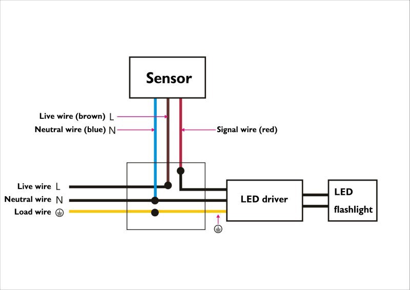
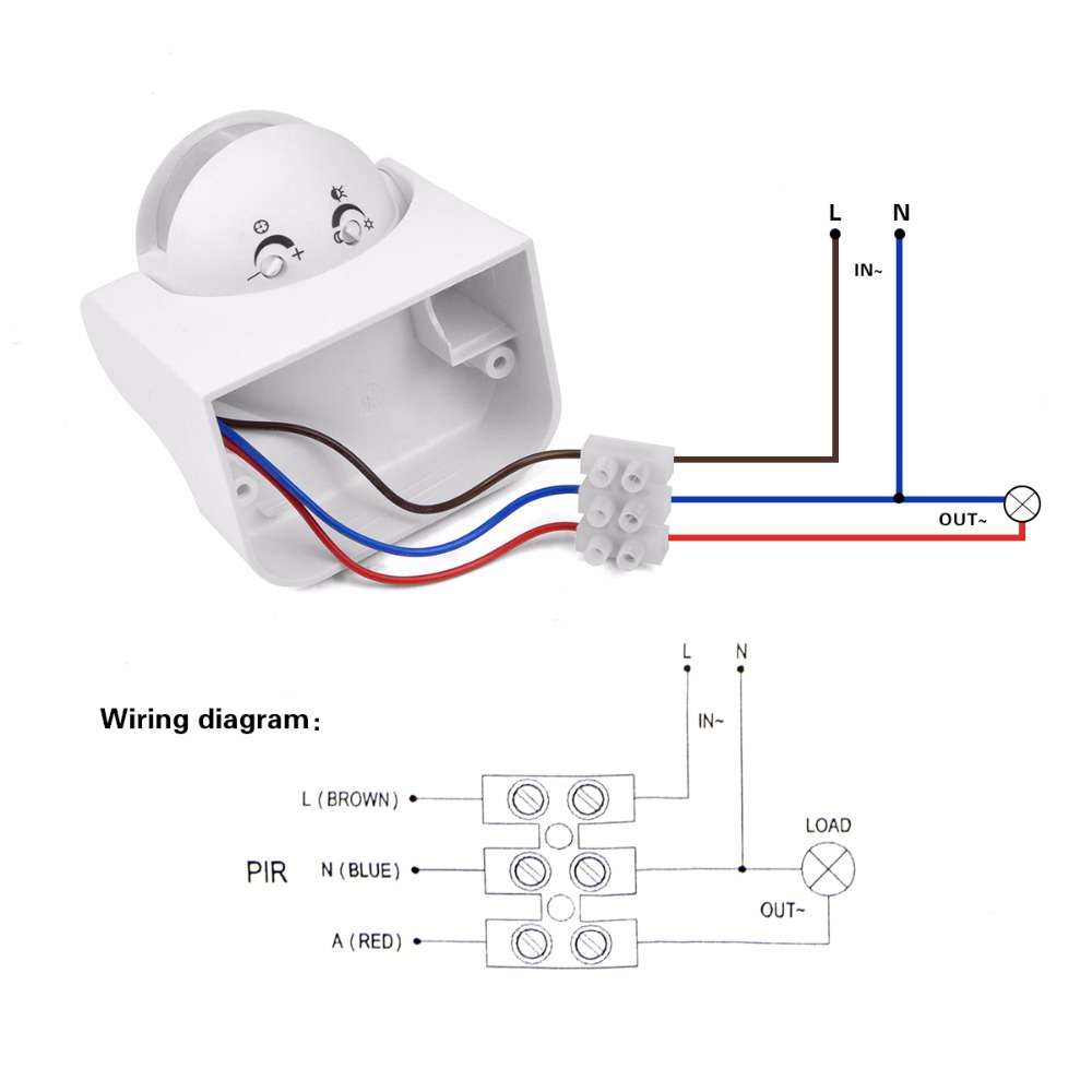
The wiring is very simple as can be seen in the picture below. Waterproof infrared pir motion sensor outdoor light with a detector for in hacks forum to an extension cord porch 220v 12v movement automatic bluestone electronics switch.
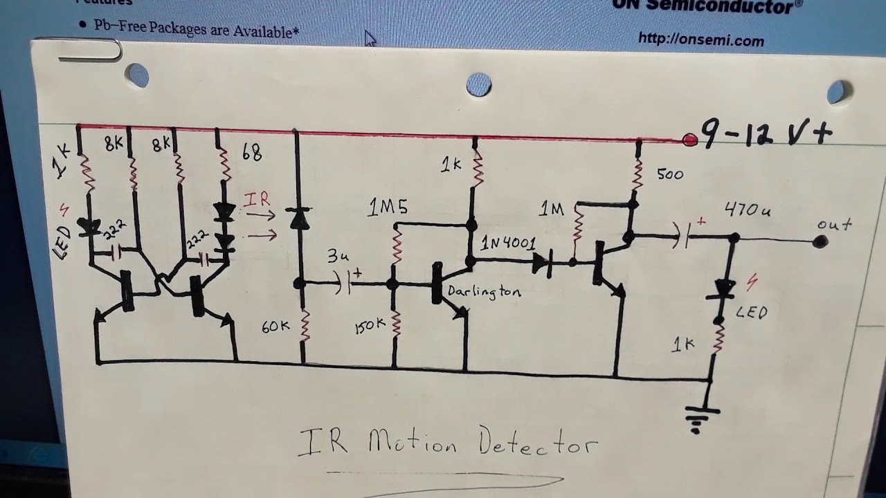
IR Motion Detector Proximity Sensor circuit diagram 2
The image shows a typical pir sensor pinout diagram.

Infrared motion sensor wiring diagram. Ir sensor is very popular sensor, which is used in many applications in electronics, like it is used in remote control system, motion detector, product counter , line follower robots , alarms etc. Wiring diagram consists of many detailed illustrations that display the relationship of varied items. And the infrared region of pir sensor is from 0 75um to 1000um.
The sensor will rotate from left to right, and tilt forward or backward. You can see the connections in the ir sensor circuit diagram. When switching to auto for any of the above configurations the infrascan will turn on.
Wiring diagram consists of numerous in depth illustrations that display the relationship of varied things. Then connect one wire to gnd and the other to an input pin on the konnected device. It consists of guidelines and diagrams for various kinds of wiring techniques along with other items like lights, home windows, etc.
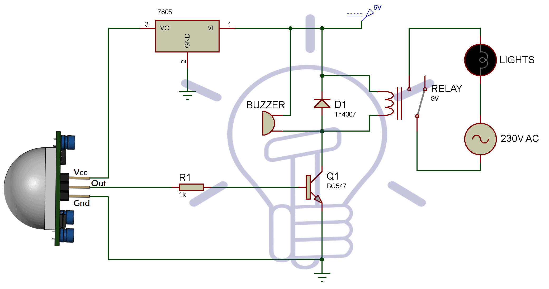
The pir sensor typically operates at 5v so we are using a positive voltage regulator ic 7805 which will give 5v output to feed the sensor. Pir sensors are more complicated than many of the other sensors explained in these tutorials (like photocells, fsrs and tilt switches) because there are multiple variables that affect the sensors input and output.to begin explaining how a basic sensor works, we'll use the rather nice diagram below (if anyone knows where it originates plz let me know). December 28, 2020 1 margaret byrd.
It's quite simple to understand the pinouts and one may easily configure them into a working circuit with the help of the following points: Major tech pir34 180 degrees 1200w infrared motion sensorbuilders war. A quick video showing you how to wire a motion sensor up to an led light.motion sensors are great in areas where a light switch is not practical.
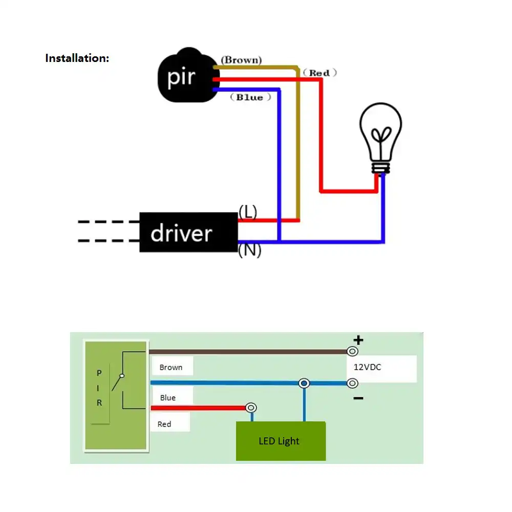
Wpr motion infrared sensor sensor, 10a, 3 wire, outdoor, grey. Now when we find the led blinking whenever there is any motion, look back of the pir, you will find a jumper which is placed between outer corner pin and middle pin (see diagram above). In this case, simply connect jumper wires to the signal pair of wires.
Automatic with manual override on or off 1c). Simply connect vcc and gnd to a battery and a red led between the output pin and ground. First of all, plug all three female pins to the pir motion sensor.
Set the two adjustment controls on the underside of the unit (diagram c) to the following positions: Motion sensor wiring diagram red blue brown. As indicated in the following diagram, pin#3 of the sensor should be connected to the ground or the negative rail of the supply.
The passive infrared sensor consists of three pins as shown below. Wiring diagram 1(a), without override switches is preferred asthere is no settling period. Once the pin motion sensor is connected to the arduino uno then we can control different loads like motors, buzzers, relays, leds, and many more.
There are three ir regions on spectrum named as near infrared 0 75 3um mid infrared 3 6um and far infrared higher than 6um. It consists of guidelines and diagrams for various kinds of wiring techniques along with other items like lights, home windows, etc. • when switching to auto for any of the above configurations the infrascan will turn on.
Pir motion sensor light wiring diagram. Pin1, pin2, and pin3 are corresponded to drain, source and ground terminal of the device. It includes guidelines and diagrams for various varieties of wiring techniques and other items like lights, home windows, and so forth.
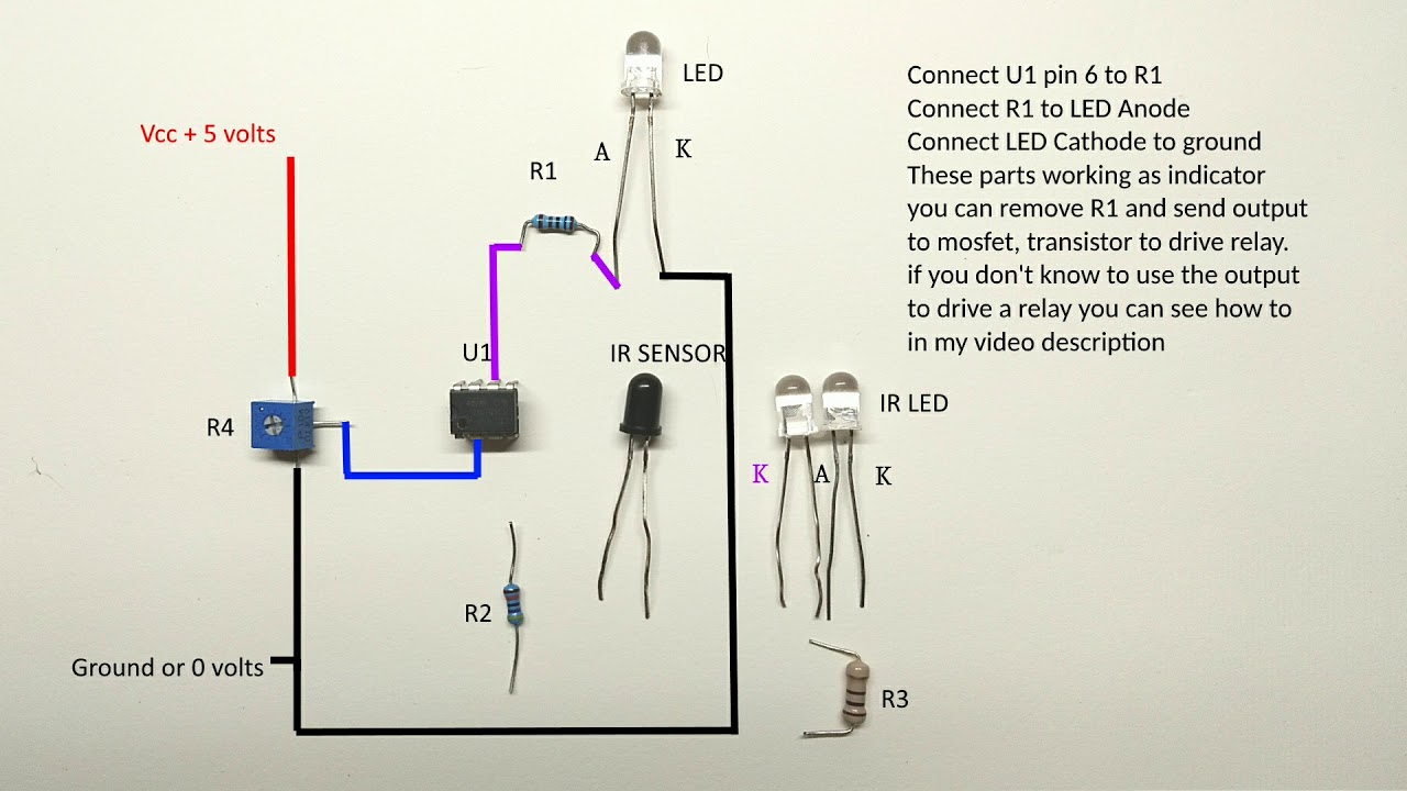
• when switching to auto for any of the above confi. The output voltage is 3.3 v, so i added a 68 ω current limiting resistor in series with the led. Adjust the sensor to point in the desired direction.
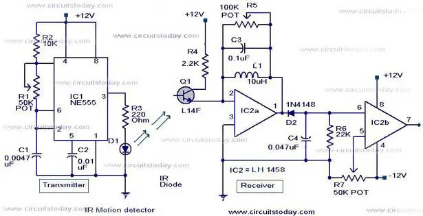
At first we will put the ic lm358 on the breadboard. Obstacle sensing circuit or ir sensor circuit. Passive infrared motion sensor motion sensor technology, the series indoor infrascan is the next generation of the constantly evolving family of clipsal pir sensing devices.
Wiring diagram consists of numerous in depth illustrations that display the relationship of varied things. Wiring motion sensors with external power. On, off or automatic operation using a 3 position switch note:
In the following wiring diagram, the connections of interfacing can be observed. † when switching to auto for any of the above confi gurations the infrascan will turn on. In this article, we will explain about ir sensor (infrared sensor), how it works and how to build an ir sensor module.
Here, the sensor data can be read through one of the gpio pins of the arduino board like digital pine2. A wiring diagram is a simplified conventional pictorial depiction of an electrical circuit. If your motion sensors are already working and wired to an existing alarm system, you can leave the power wires (usually red and black) connected to the existing power.
30 watt led motion detector light pic or wires Handyman
4 Wire Motion Sensor Light Switch Wiring Diagram Wiring

Infrared Motion Detector schema diagram

PIR Motion Sensor Light Switch Motion Sensor PIR Light
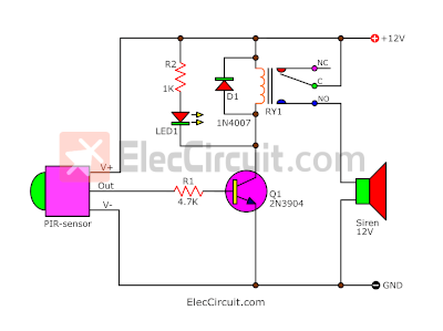
Motion detector alarm circuit with PIR sensor Simple and

Build a Passive Infrared Sensor Circuit Diagram
IR (Infrared) Detector Circuit Diagram using 555 Timer IC

Motion Sensor Wiring Diagram Wiring Diagram
34 Motion Sensor Diagram Wiring Diagram Database
Infrared Motion Detector Circuit Circuit Diagram
How To Wire A Light Motion Sensor Nice Pir Security Light


PIR Sensor Based Motion Detector/Sensor Circuit Circuit

IR Sensor Circuit and Working with Applications Circuit
Long range infrared sensor circuit diagram YouTube
Infrared Motion Detector CircuitIR motion sensor circuit

Infrared Motion Sensor Wiring Diagram

IR Sensor Module Circuit Electronic circuit projects
Pir Motion Sensor Light Wiring Diagram Wiring Diagram


infrared sensor interfacing with Arduino and PIC16F77A