
In the first example, i will show you how. Tb6600 stepper motor driver / controller vcc pin (red wire in the diagram).
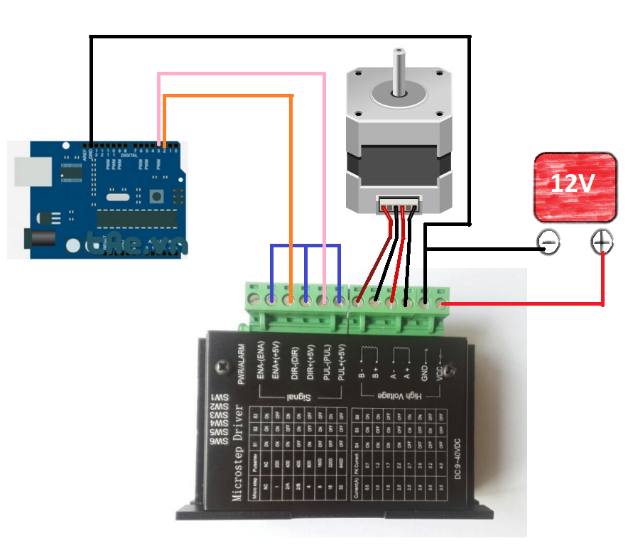
Wiring Diagram Dm542t
High level (npn control signal, pnp and differential control signals are on the contrary, namely low level for enabling.) for enabling the driver and low level for disabling the driver.

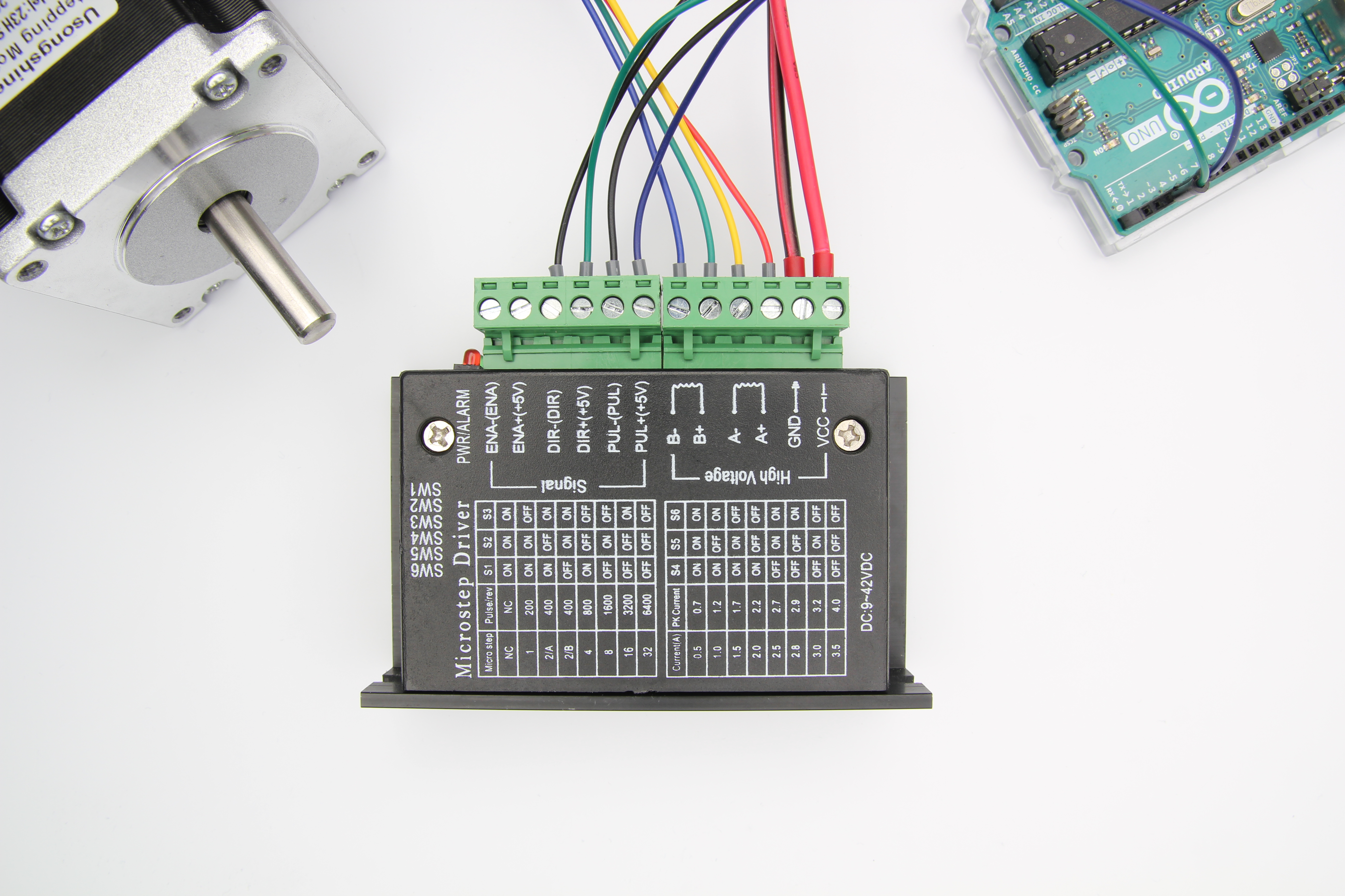
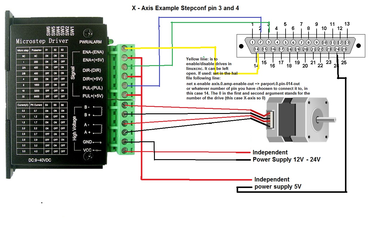
Microstep driver wiring diagram. It supports speed and direction control. This driver is easy to use and can control large stepper motors like a 3 a nema 23. You can set its micro step and output current with 6 dip switches.
In setting the driver output current, multiply the specified phase current by 1.4 to determine the peak output current. Wiring diagrams for 4/6/8 leads motors i. This example can be used to let the motor spin continuously.
In setting the driver output current, multiply the specified phase current by 1.4 to 5)it is forbidden to add the tin wire to the terminal after adding the tin wire. There are 7 kinds of micro steps (1, 2 / a, 2 / b, 4, 8, 16, 32) and 8 kinds of current control (0.5a, 1a, 1.5a, 2a, 2.5a, 2.8a, 3.0a, 3.5a) in all.
This signal is used for enabling/disabling the driver. When the charged motor stops, there is still a large current flowing through the coil. Speed and torque will depend on winding dm556 digital stepping driver manual v1.0 tel:
I have included a wiring diagram and 3 example codes. Two wires for a coil to the driver will reverse motion direction. The wiring diagram below shows you which connections you need to make.
Connecting the tb6600 stepper motor driver to an arduino and stepper motor is fairly. In the first example, i will show you how you can use this stepper motor driver without an arduino library. Usually left unconnected (enabled) 2) pins wiring diagram:
Speed and torque will depend on winding inductance. High level (npn control signal, pnp and differential control signals are on the contrary, namely low level for enabling.) for enabling the driver and low level for disabling the driver. 4 lead motors are the least flexible but easiest to wire.
Pc’s control signals can be active in high and low electrical level. Wiring instructions there are three input signals in all: Tb6600 stepper motor driver with arduino uno and stepper motor wiring diagram.
Two wires for a coil to the driver will reverse motion direction. Wiring the stepper motor to the cw230 driver, wiring the cw230 driver to the parallel. Wiring for nema 24 stepping motor to microstep driver cw230.
4)it is forbidden to plug and unplug the driver's strong p2 terminal. Speed and torque will depend on winding inductance. In this tutorial, we will be connecting the driver in a common cathode conguration.
Microstep steps/rev.(for1.8°motor) sw5 sw6 sw7 sw8 2 400 4 800 8 1600 16 3200 32 6400 64 12800 128 25600 5 1000 10 2000 20 4000 25 5000 40 8000 50 10000 100 20000 125 25000. Microstep steps/rev.(for1.8°motor) sw5 sw6 sw7 sw8 2 400 on on on on 4 800 on off on on 8 1600 on on off on 16 3200 on off off on 32 6400 on on on off 64 12800 on off on off 128 25600 on on off off 256 51200 on off off off 5 1000 off on on on 10 2000 off off on on 25 5000 off on off on 50 10000 off off off on 125 25000 off on on off 250 50000. High level for enabling the driver and low level for disabling the driver.
Pulling the p2 terminal will cause a huge moment to induce the electromotive force to burn the driver. You can set its micro step and output current with 6 dip swit. The output of the 3.3 vdc dc to dc converter is routed to pins 2, 4 and 6 of the tb6600 stepper motor driver / controller (blue wire in the diagram).
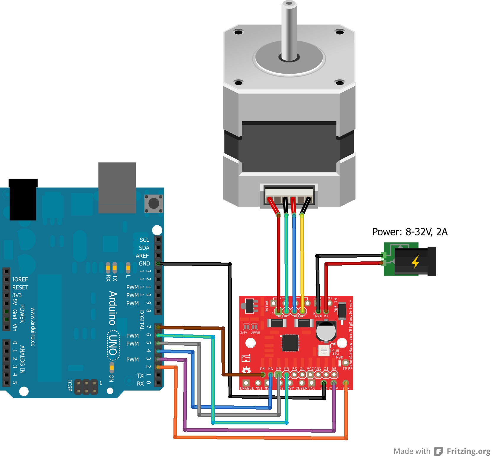
In this tutorial, you will learn how to control a stepper motor with the tb6600 microstepping driver and arduino. Tb6600 stepper motor driver with arduino tutorial. I have included a wiring diagram and 3 example codes.
This driver is easy to use and can control large stepper motors like a 3 a nema 23. This signal is used for enabling/disabling the driver. It is also routed to the input of the 3.3 vdc dc to dc converter (again a red wire in the diagram).
It supports speed and direction control.
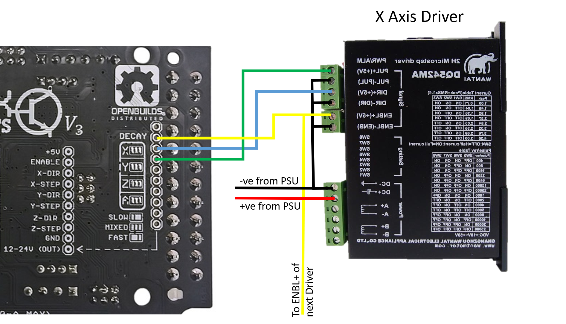
C3D External Stepper Driver Wiring Diagrams


3 Axis CNC Controller Kit Nema23 Stepper Motor 175 Ozin
4 Achse CNC Steuerung Set Nema23 Schrittmotor 175 Ozin
.png)
DQ542 Drivers Protoneer Product Forum

TB6600steppermotordriverwithArduinoUNOwiring
TB6600 Stepper Motor Driver with Arduino Tutorial (3 Examples)

Épinglé sur Proxxon MF 70

[DIAGRAM] Three Phase Home Wiring Diagram FULL Version HD
Stepper motor not rotating, just sounds like it is going

Lerdge External High Power Switching Motor Driver Adapter
.jpg)
3.3Nm Nema24 Stepper Motor CNC Kit 3 Axis TB6600HG Stepper

Robot using stepper motors and TB6600 driver
Mạch Điều Khiển Động Cơ Bước TB6600 Truong An Electronics
Hooking Up External Drivers to the CNC xPRO V3 Spark
Easydriver how to get it to work? Page 2 LinuxCNC

Micro Step Motor Driver Speed Controller Module Board DC
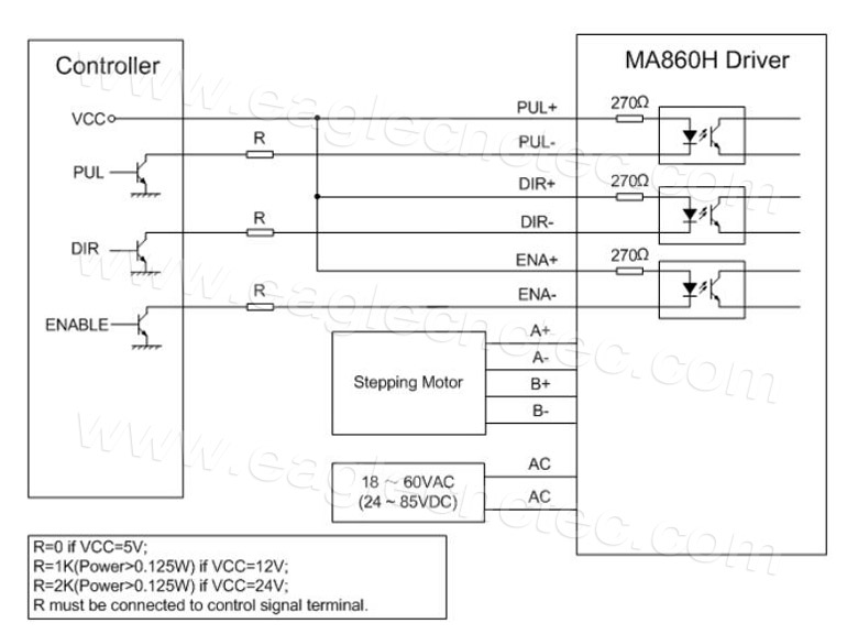
Microstep Driver Leadshine MA860H DM1182 Stepper Motor Driver

Koračni Motori & Drajveri TB67S Stepper Driver
M335 CNC Stepper Driver 2/4 Phase 16 Microstep Multiple
.jpg)