The diagram below shows the dimensions (in mm) of the 37d mm line of this header works with standard ″ male headers and our male jumper and precrimped wires. 3 x jumper wires wiring diagram.
Digital Encoder Circuit diagram Using Stepper Motor under
9 orange 7 blue 5 yellow 3 red lead wire color sxxx, mxxx encoder, cable p/n:

Motor encoder wiring diagram. Three of them on encoder side while two on the click button side. You should show which mlfb is on the cable because with this mlfb you can decode which encoder wiring is used. Caution when wiring for differential applications (a,a,b,b,z,z), a and a.
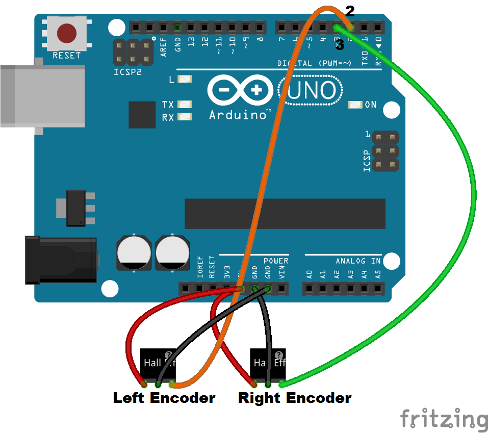
Note that the encoder pin outa needs to be connected to a hardware interrupt pin (digital pin 2 or 3 on an arduino duemilanove or uno). As the wiring diagram shows you’ll need a servo motor. Construction of ac servo motor.
Logical expression for a1 and a0. Connection wiring diagram • 8 lead wire type black red white brown blue yellow orange green a b a b • 6 lead wire type [( ): The circuit is designed to give control signals to the servoic1 is designed as an astable multi vibrator which can give pulses for the operation of the servo.
Using a voltmeter, i determined 0 voltage was present on terminal c, (circuit 241, brown wire). 3a, 3b), the 1220’s keyswitch power must go through the traction controller so that when the keyswitch is turned off both controllers turn off. 2020 popular fanuc encoder trends in home improvement, tools, security & protection, electronic components & supplies with fanuc encoder and fanuc encoder.
As stated, the rotary encoder has 2 coding pins that are either high (1) or low (0). These or gates encode the eight inputs with three bits. Zxy6000 power conversion described in detail :for the interface diagram when you need to use modified font has been marked in yellow , the cable can be.
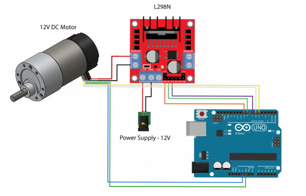
Connect the red wire of the servo motor to the external 5v supply, the black/brown wire to ground and the orange/yellow wire to the pwm enabled pin 9. See the diagram below for details on wiring up the encoder for motor b, and repeat for motor a. See connector options and wiring diagrams.
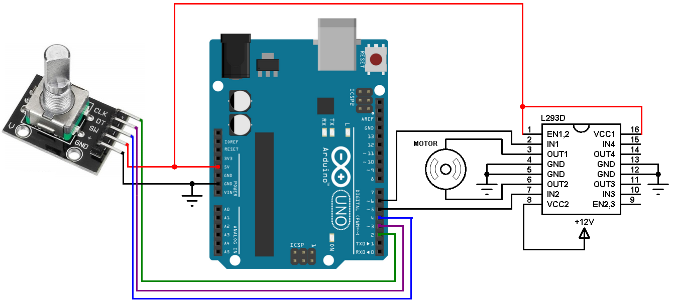
I chose this wire based on the wiring diagram, which showed fuse 24 in the ip fuse box feeding voltage to the front axle motor. Motor control tutorial you can find the circuit schematics for connecting the driver and the stepper motor.rotary encoder has 5 pins; The circuit diagram for a 4 to 2 line encoder is shown below octal to binary encoder.
However you need to pay attention to wire polarity. Pin number] wiring diagram b a red (3) white (2) blue (1) (4) black (5) yellow (6) green b a pin assignments of pk244pa , pk246pa (6)·····(1) pk244pa and pk246pa are connector type motor. Going this far without first checking the fuse could turn out to be pretty embarrassing if the
Controller wiring controller wiring as shown in the wiring diagrams (figs. The type designation of encoders from sew‑eurodrive consists of 4 characters, the inverter and the wiring diagrams supplied with the encoders. 3aasic wiring diagram, using motor encoder for feedback device.b 2 — installation & wiring:
Wiring diagram forwiresaving motor encoder figure 3.4 wiring diagram forwire saving motor encoder 伺服驱动器 servo driver 伺服电机servo motor 伺服电机插座 servo motor socket 省线式伺服电机编码器 wire saving servo motor encoder awire saving encodershould be selected for servo motors below 80series Working of ht12e encoder ic gadgetronicx. Mg996r servo motor wiring diagram click the image to enlarge it the mg996r is a metal gear servo motor with a maximum stall torque of 11 kg cm.
The wiring depends not on the connector , this connector can be used for a lot of encoders. If you have a reading of 01, the next reading can either be 00 or 11 depending on the direction the knob is turned. Servo motor wiring diagram zm056 series solid od 56mm servo motor encode slip ring drawing.
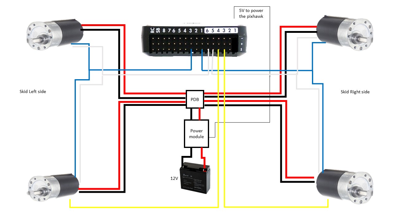
01 silverado encoder wiring diagram. Wiring for a single motor and encoder. The schematic diagram of servo system for ac two phase induction motor is shown in the figure below.
Motor cable encoder cables cable p/n: If you treat the pins as binary, you can read them as 00, 01, 10, or 11 (sequence the encoder outputs while spinning clockwise is 00, 01, 11, 10). The dealer tells me the encoder motor needs to be replaced.
The two (1 & 2) pins are actually push buttons where 1 is grounded and 2 acts like a switch while on encoder side the corner pins (3 & 5) are connected to the arduino board. • connect the m12 connector as shown in the wiring diagram. Encoder wiring schemes can be unique to each encoder and one should follow the diagram or pinout designated on the encoder datasheet.
Ht12e encoder and decoder schematic diagram scientific. Green red yellow white black lead wire color manufacturer: The following diagram depicts the block diagram of an octal to binary encoder.
• wire the connection box [] (in accordance with the previously installed encoder type). Wiring up the encoders is pretty simple. Mabuchi motor encoder dc 12 volt wiring diagram this gearmotor is a powerful 12v brushed dc motor with a metal gearbox 37d mm metal gearmotor with 64 cpr encoder (no end cap).
New servo wiring diagram arduino diagram diagramtemplate diagramsample. 2 wires to power the encoder (often labeled gnd and 3.3v) 2 wires to send signal of position to the microcontroller (arduino) (labeled as encoder output or c1 & c2) first you will connect 2 wires to power the encoder to arduino gnd and vcc 3.3v (in my version of encoder motor, the encoder led turn on when i connected the wire power) then. It says to put the transfer case in neutral, which i can't electronically have a wiring diagram of the 8 pin connector at the sensor motor i need to.
Front axle motor actuator next.
Simple Motor Optical Encoder Schematic PyroElectro

Arduino Stepper motor control with rotary encoder Simple

Help Wiring brushless motor with building encoder
Motor Encoders with Arduino Bot BlogBot Blog

Como usar motor DC com encoder no Arduino Arduino e Cia

Wiring the encoders with Arduino ESP8266 Robotics Projects

370 Motor Hall Encoder DC 2.5V24V 12 PPR Dual Quadrature
How to test motor encoder with Arduino «

DC Motor control with rotary encoder and Arduino Simple

Circuit diagram for motor encoder · Issue 1 · agnunez

Motor With Encoder, How to Read Input Value From Encoder

DC Motor control with rotary encoder and PIC MCU mikroC

Solved Given The Schematic Of A DC Motor With Encoder Con

Quadrature encoder signal from dc motor is very noisy

DC Motor speed/direction control using PIC16F877A and


