• the activation of loads parallel to the start input is not permissible when using ac control voltage (see diagram below). The input sighal is invalid if it gets a trigger signal again during delay time op.

Simple Delay Timer Circuits Explained
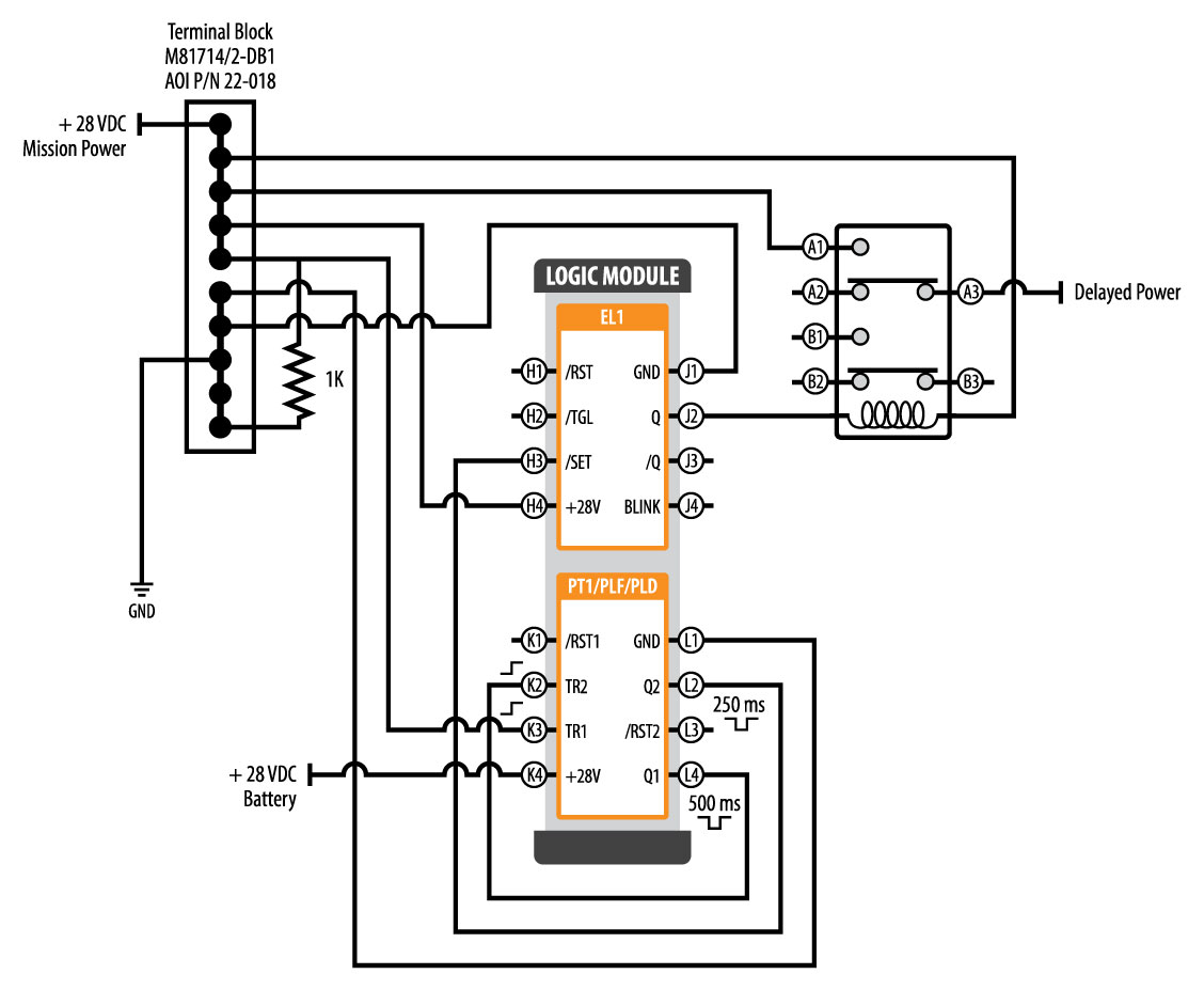
The timer function #1 is on delay, it allows to supply power after a period of time (t).

Timer delay relay wiring diagram. Time delay relays have a broad choice of timing ranges from less than one second to many days. The input sighal is invalid if it gets a trigger signal again during delay time op. Control voltage applied to the input terminals (see wiring diagrams below).
• off delay timers are with aux. Single pole contactor relay wiring diagram 240v single pole means that it can only control a single circuit and single throw means that there are only two positions the switch can be in one on and one off state mechanical relays do not the esd5 series is an accurate solid state delayed interval timer it offers a 1a steady 10a inrush. Control voltage applied to the input terminals (see wiring diagrams below).
Assortment of 12 volt relay wiring diagram. On delay timer circuit diagram wiring diagram contactor with push button circuit diagram of delay timer on off power off delay timer circuit diagram 2 way lighting circuit triggering transformer push button fan switch light activated switch circuit diagram wd081 text. What this circuit will do is that it will delay my push button action so the power will remain on to the pump for 5 seconds then turn of instead of the push button will only power while pressed.
Relay will turn on for time op after getting a trigger signal and then turn relay off.the module will restart timing if it gets a trigger signal again during delay time op. 1 on delay voltage, the time relay (t) upon application of input begins. There are two timing charts, one without a trigger and one with the trigger.
Star delta features mono function timer range 80 61 true off delay multi voltage. October 19 2019 1 margaret byrd. At the end of the time delay (t), the output is energized.
Hager eh011 timer wiring diagram. Same potential must be applied to a1 and b1, or a3 and b3. A relay is an electrically operated switch.
Hager timer switch wiring diagram. Finder relays types 45 91 56 xx 0300 62 xx 0300 and. Timer switch circuit diagram for light circuit diagram electrical circuit diagram simple circuit.
8 timed flasher voltage, time delay (t2) (on first) upon application of begins and the output is energized for the time delay (t1). On time delay relays, the. The timer function #1 is on delay, it allows to supply power after a period of time (t).
When the set time has elapsed, the relay contacts transfer to the on state. Another image hagar eh connected to 3 phase v must have line fuse or fuse carrier installed to protect timer and wires to timer. At the end of the time delay (t1), the output is energized and the
8 pin timer relay wiring diagram | basic timer connection and function |three phase main distribution board wiring | 3 phase distribution mdb box wiring diag. The timer is reset by removing the coil voltage. Ah3 delay timer and relay electrical circuit diagram electrical wiring diagram hvac design ah3 delay timer wiring with push button electrical circuit diagram timer basic electrical wiring bathroom fan and light switch wiring diagram bookingritzcarlton info bathroom fan light bathroom exhaust fan light exhaust fan
Star delta starter wiring diagram 3 phase with timer electrical online 4u electrical. Voltage (refer wiring diagram fig.1). The difference between relays and time delay relays is when the output contacts open & close:
Ah3 delay timer and relay electricity timer electrical projects. The contacts remain in the on state until the timer is reset. Such relays are called time delay relays.
Relay and contactor wiring diagram. 16 doerr electric motor wiring diagram wiring diagram wiringg net circuit diagram electrical diagram electrical circuit diagram. This post is about the staircase timer wiring diagram in the diagram i use the on delay timer finder 8 pin relay re electrical circuit diagram timer diagram
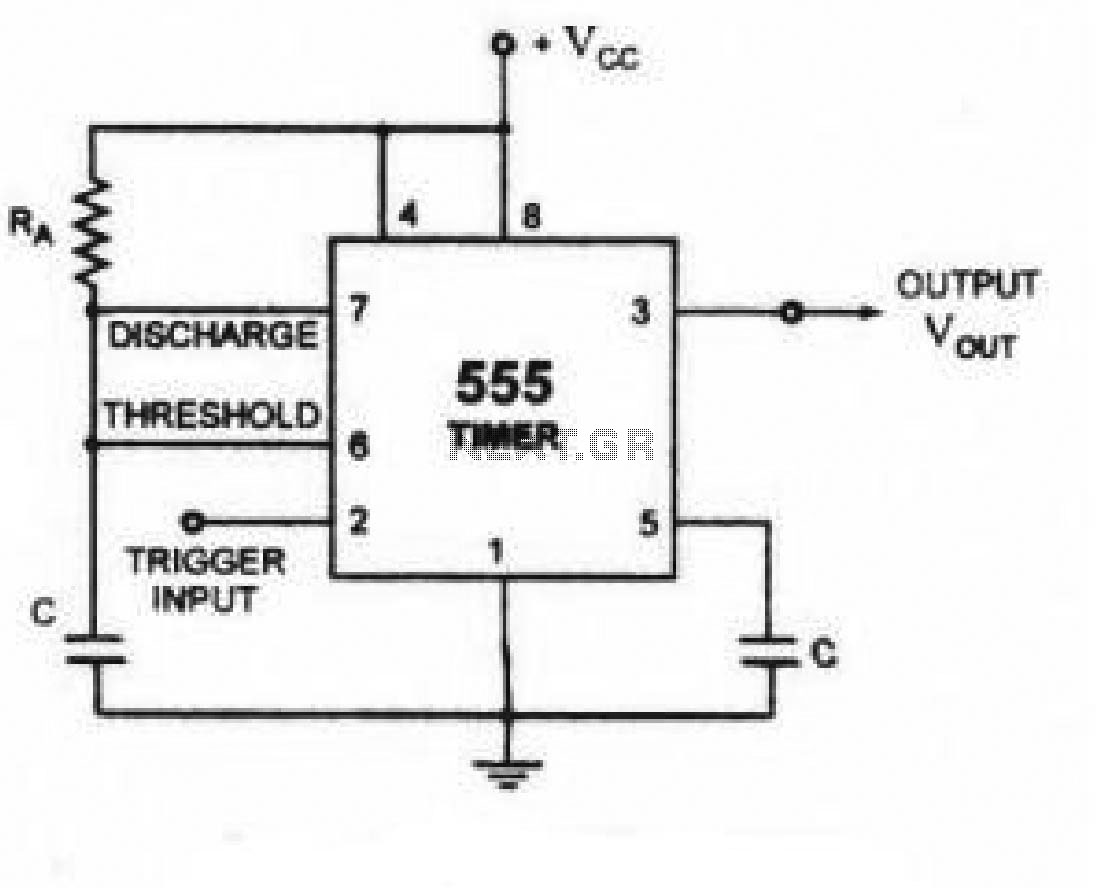
Relay will turn on for time op after getting a trigger signal and then turn relay off. Trigger selection can be done during timer configuration. Solid state timer relay time delay circuit with 555 8 pin wiring diagram using ic digital 12v 24v 326 327 series relays on dc 110 super asymmetric cycler best supplier in multi functional motor control systems part c driving a thermostat ics module applications and to cycle traffic signal led home automation double factory arduino variable connections of external three motors 2 10.
Each component should be placed and linked to other parts in particular manner. Continuous relay on blinking relay off type 13 81 4 wire connection red led indication. Time delay relays have a broad choice of timing ranges from less than one second to many days.
Schneider electric low voltage distribution cct15232 mins timer 05 20min. On a control relay, it happens when voltage is applied and removed from the coil; Time relay 230v ac ezn001 hager relays eibabo com.
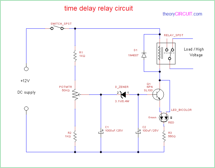
A time delay relay consists of a normal electromechanical relay along with a control circuit to control the relay operation and timing. Full size image 11 pin timer wiring example 8 pin wiring for relay in sprinkler system how to wire pin timers at off delay timer wiring diagram. Relay will turn on for time op after getting a trigger signal and then turn relay off.
Relay will turn on for time op after getting a trigger signal and then turn relay off.the module will restart timing if it gets a trigger signal again during delay time op. This post is about the staircase timer wiring diagram in the diagram i use the on delay timer finder 8 pin relay re electrical circuit diagram timer diagram.

Dayton Time Delay Relay Wiring Diagram Gallery
How To Build Time Delay Relay Circuit

Dayton Time Delay Relay Wiring Diagram Gallery
Dayton Time Delay Relay Wiring Diagram A652

Dayton Time Delay Relay Wiring Diagram A652

Dayton Time Delay Relay Wiring Diagram Gallery

Dayton Time Delay Relay Wiring Diagram Gallery
20 Elegant Time Delay Relay Wiring Diagram

Time Delay Relay Wiring Diagram Free Wiring Diagram

Dayton Time Delay Relay Wiring Diagram A652

Delay On Break Timer Wiring Diagram

Dayton Off Delay Timer Wiring Diagram Collection

Solid State Timer Solid State Relay Timer Electrical
Golden Fuel Systems Switch Delay Relay Wiring Diagram
60 Best Of Time Delay Relay Wiring Diagram

Relay OFF Time delay timer by using NPN Transistor and

Dayton Off Delay Timer Wiring Diagram Collection


