
Assortment of 3 phase 6 lead motor wiring diagram. You may be able to understand precisely if the projects should be completed, that makes it much easier to suit your needs to correctly control your time and effort.
6 Lead Motor Wiring Diagram
63a, 30ma trip current (rcd/gfci):

3 phase motor wiring diagram 6 wire. The motor will supply the same amount of power but with a different load amperage. Running a three phase 480 volt motor on single phase 120 volt diy electronics motor wire. You may be able to understand precisely if the projects should be completed, that makes it much easier to suit your needs to correctly control your time and effort.
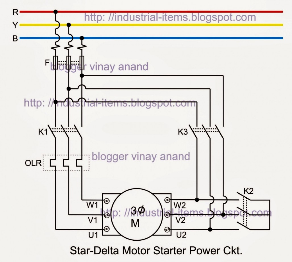
If you need to remove any file please contact original image uploader. But i assume you have not found the wires yet. Delta run for low voltage and wye run for high voltage.
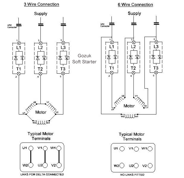
How the wires are interconnected dictates the voltage being supplied to the motor. This motor is a 6 lead dual voltage motor. Revealing four wires inside cord.
June 6, 2021 on 480v 3 phase 6 lead motor wiring diagram. 3 phase motor wiring diagram 6 wire. In the united states, for low voltage motors (below 600v), you can expect either 230v or 460v.
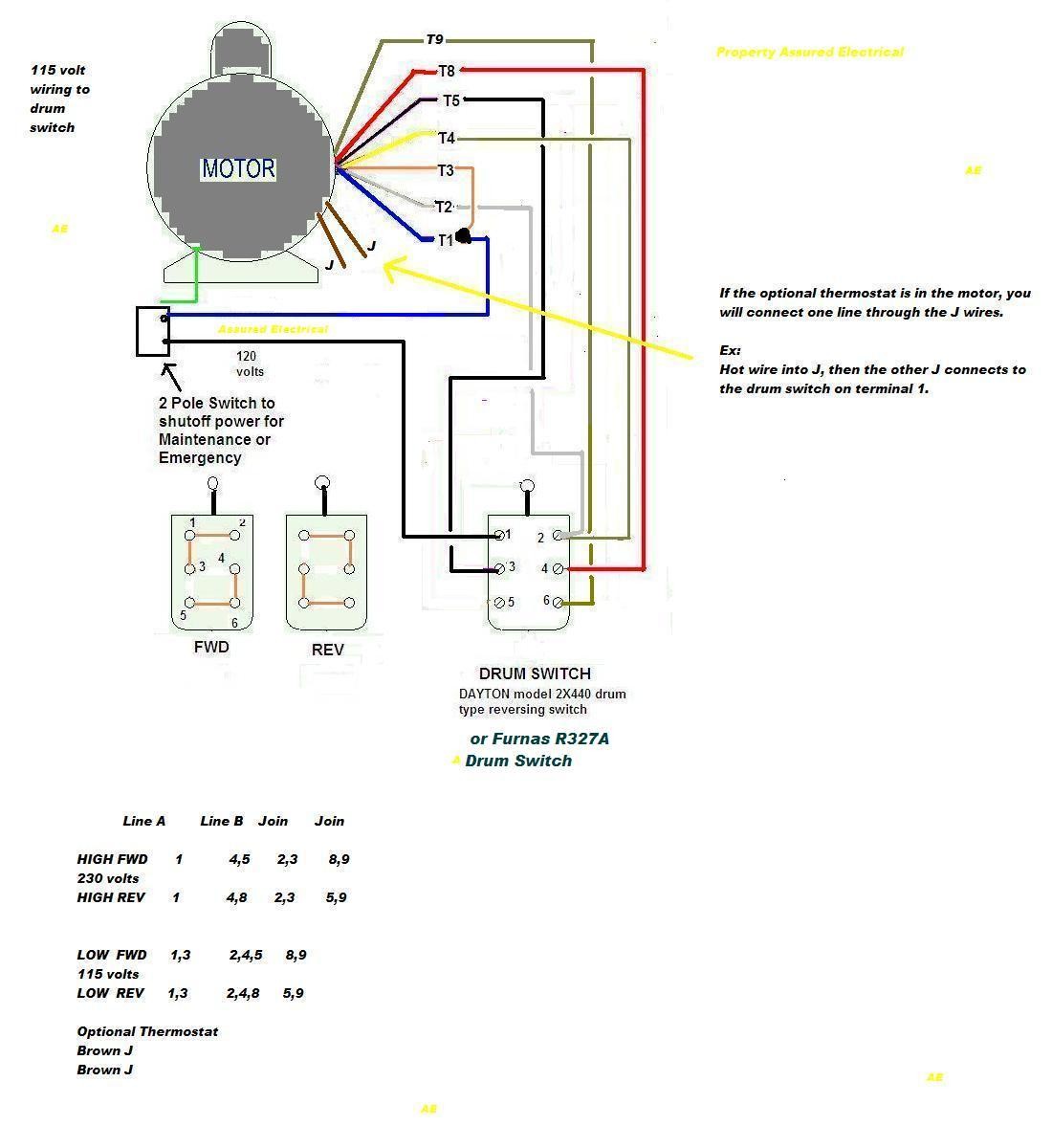
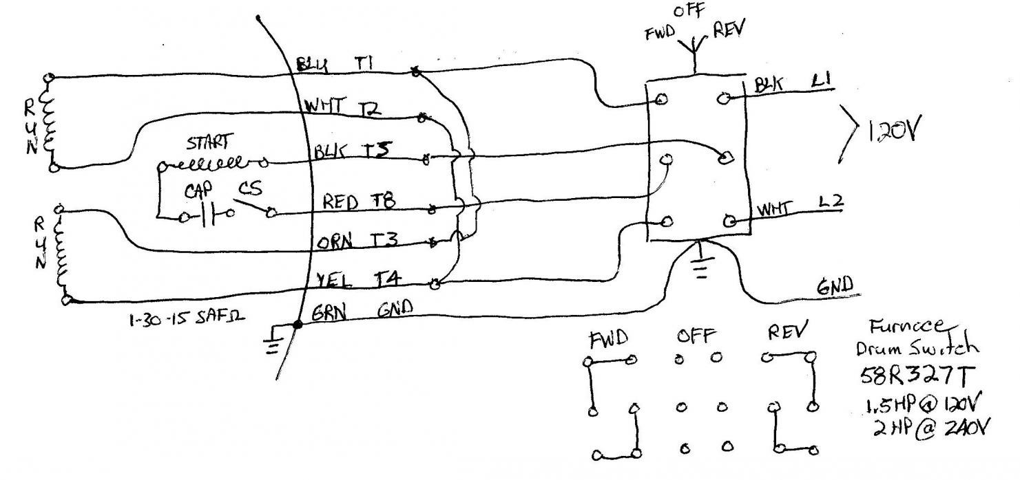
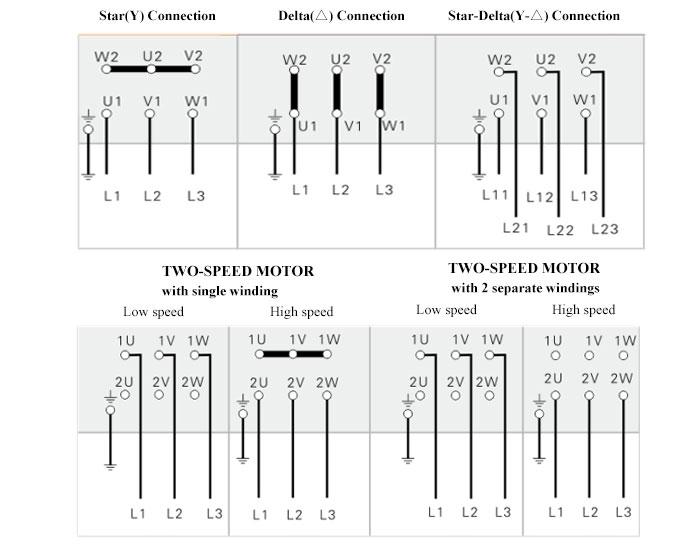
The supply voltage is either 240 volts alternating current (vac) or 480 vac. W2 cj2 ui vi wi w2 cj2 ui vi wi a cow voltage y high voltage z t4 til t12 10 til t4 t5 ali l2 t12 ti blu t2 wht t3 org t4 yel t5 blk t6 gry t7 pnk. My whole point with my comments is that the name plate shows the motor as a 480/240 volt motor.
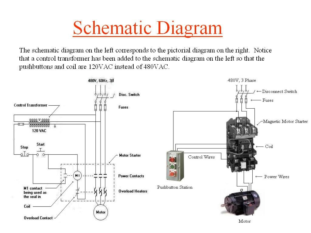
They can also be found in large residential complexes and appliances requiring a large amount of power. I am trying to wire up a two speed 6 wire 3 phase motor to run at it's highest speed. It reveals the elements of the circuit as streamlined forms and also the power and signal links in between the tools.
Diagram dd6 diagram dd8 m 1~ ln e diagram dd9 m 1~ ln e white brown blue l1 l2 n s/c bridge l1 and l2 if speed controller (s/c) is not required diagram dd7 ln e l1 l2 n s/c z2 u2 z1 u1 cap. October 11, 2021 on 3 phase motor wiring diagram 6 wire. But, it doesn’t imply link between the cables.
The start in series with a cap would be connected across one of the other windings, never across full volts in high voltage mode. Using a pair of diagonal cutters, cut and remove 3 in of rubber insulation around outside of power cord. 3 inches (7.6 cm) of insulation from the outside of the four lines located within the power cord.
At times, the cables will cross. In this tutorial, we need the following wiring accessories to wire three phase power in home. Print the wiring diagram off plus use highlighters to trace the signal.
I'm sure that the motor is listed and tested for those voltages, but a 2 to 1 voltage change is not possible with a 6 lead 3 phase motor. Three pole mccb, 63a (100 or 250a in us) : Diagram dd6 diagram dd7 m 1~ ln e diagram dd8 ln e l1 l2 l3 s/c z1 u2 z2 u1 cap.
1 trick that we 2 to printing a. Typical wiring diagram line diagrams show circuits of the operation of the controller. Below is the motor data plate and what's left of the wiring diagram.
When you make use of your finger or perhaps the actual circuit with your eyes, it is easy to mistrace the circuit. I think i have this right, but it's always best to check before applying power. Make sure that the voltage you will be.
You will be in a position to learn precisely when the projects needs to be completed, which makes it easier to suit your needs to properly control your time. Those nine leads provide an option for supplying power from either high or low voltage sources. How the wires are interconnected dictates the voltage being supplied to the motor.
Injunction of two wires is generally indicated by black dot on the intersection of 2 lines. For the low voltage option, the instructions show to connect the following: The motor will supply the same amount of power, but with a different load amperage.
You’ll be capable to understand exactly once the assignments needs to be accomplished, which makes it much easier for you to correctly handle your time and effort. The higher the voltage, the lower the amperage. The first step is to figure out the voltage of your phases.
The standard 2 voltage 1 phase motor would have 2 run and one start winding. I believe i need to wire u1, v1, w1 to power and leave u2, v2, w2 disconnected. As stated previous, the lines at a 3 phase 6 lead motor wiring diagram represents wires.
That being said, there is a wide range of different motors and what you have on hand can be completely different. The data plate shows an apparent 3 phase setup. 3 phase motor schematic diagram 220v and 440 v motor diagram metal working data 3 phase to 1 phase wiring diagram in 2021 electrical circuit diagram electrical diagram diagram starting capacitor wiring diagram with single phase motor start at circuit diagram electrical diagram electrical circuit diagram
480 Volt 3 Phase 6 Lead Motor Wiring Diagram Connecting
3 Phase 6 Lead Motor Wiring Diagram — UNTPIKAPPS

480v 3 Phase 6 Lead Motor Wiring Diagram Wiring Diagram
3 Phase 6 Lead Motor Wiring Diagram Wiring Diagram
![]()
3 Phase 6 Lead Motor Wiring Diagram Wiring Diagram

3 Phase Motor Wiring Diagram 6 Wire Collection Wiring
6 Lead 3 Phase Motor Wiring Diagram 6 Wire Wiring

3 Phase 6 Lead Motor Wiring Diagram Free Wiring Diagram
230 Volt 3 Phase 6 Lead Motor Wiring Diagram All Replies


6 Lead 3 Phase Motor Wiring Diagram 6 Wire Wiring

3 Phase 6 Lead Motor Wiring Diagram Database Wiring
480v 3 Phase 6 Lead Motor Wiring Diagram Wiring Diagram


Three Phase 3 Phase Motor Wiring Diagram 6 Wire For Your Needs
6 Lead 3 Phase Motor Wiring Diagram / Diagram Wiring

3 Phase Motor Wiring Diagram 6 Wire For Your Needs
3 hp (2.2kW) 3 phase 6 pole AC Induction Motor
12 Lead 480 Volt Motor Wiring 480v 3 Phase 6 Lead Motor

6 Lead 3 Phase Motor Wiring Diagram How To Wire 3 Phase

6 Lead 3 Phase Motor Wiring Diagram 6 Wire Wiring