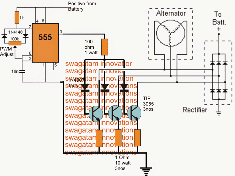
You need a lighting coil to supply an ac current that the rectifier will convert to a dc. Behind exasperating to remove, replace or repair the wiring in an automobile, having an accurate and detailed 4 pin regulator rectifier.
bike rectifier circuit diagram Wiring Diagram and Schematics
The casing does not need to be grounded.

4 wire regulator rectifier wiring diagram. Trail tech stators have yellow lighting leads. 6 volt solid state regulator rectifier. April 26, 2021 on 4 pin regulator rectifier wiring diagram.
Wiring diagram regulator rectifier full adding a battery to my startv bike 250cc gy6 harley wire 4 lawn mower atv 110cc pin half wave 12v understanding motorcycle voltage 750 regulater honda cb 3 phase 6 hd 2xchinese scooter 49cc mini chopper data vz 2185 garmin striker lighting stator 1 vs 2. Otherwise, the arrangement will not work as it ought to be. See more articles in category:
Simple 4 wire alternator wiring diagram. The diagram offers visual representation of the electrical structure. Auto parts accessories 4 wire full motorcycle regulator rectifier tester voltage wiring harley a for mosfet kawasaki 6 universal 12 volt units atv gy6 50 150cc scooter wires 5 2 phase pma install too high 3 and rectifiers wave black motored pins flwd suzuki 32800 30b01 12v lucas regulators diagram pin with.
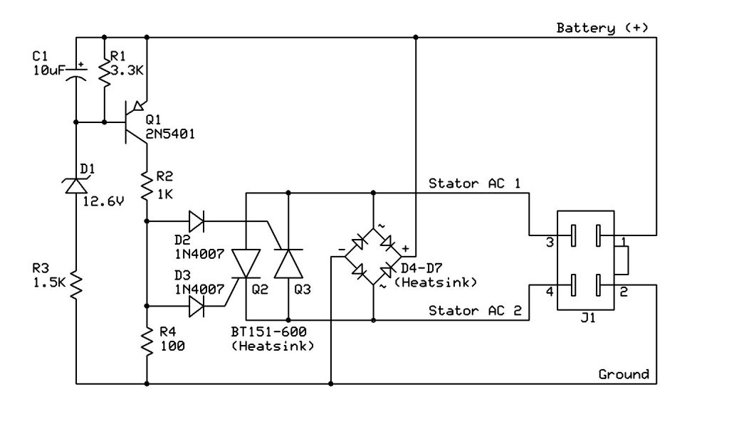
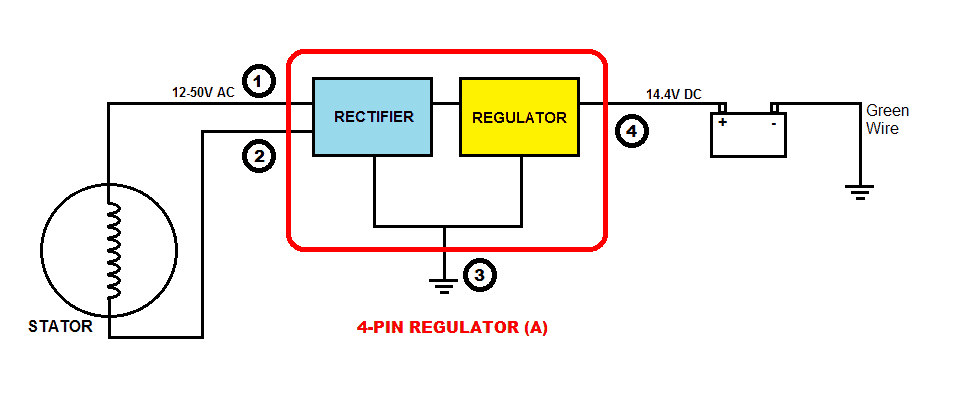
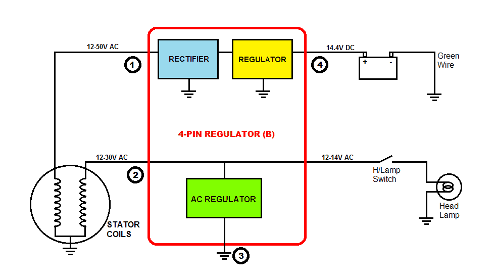
In this system, both the ends of the winding go to the rectifier section which converts ac to dc voltage and then the regulator section regulates to 14.4v as discussed above. Provided below is an online pdf document for lamberts bikes 3 phase 6 wire regulator rectifier wiring diagram. Use included wire with eye terminal to ground out the green wire on the regulator rectifier.
A few notes i pulled this schematic out of an older scooter repair manual. View lamberts bikes 4 pin motorcycle regulator rectifier wiring diagram. Regulator rectifier diagram here you are at our site this is images about regulator rectifier diagram posted by maria nieto in wiring category on may 08 2019.
Adding a regulator rectifier to an outboard motor so you can charge a battery is a relatively simple job. Yamaha outboard rectifier wiring diagram. 5 wire regulator rectifier wiring diagram 3 pin regulator rectifier wiring diagram 3 wire rectifier diagram kbpc5010 bridge rectifier wiring diagram how to wire stator and rectifier 12v rectifier regulator diagram motorcycle.
In the manner of grating to remove, replace or repair the wiring in an automobile, having an accurate and detailed 5 wire regulator rectifier. Referring the the ubiquitous 200 page service and repair manual that's floating around in pdf format, i went to page 156 (chapter 14: Many rick s motorsport electrics rectifier regulators eliminate what is commonly referred to as a signal wire on oe pieces.
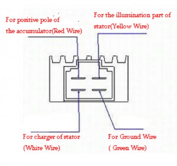
4 pin regulator rectifier wiring diagram from. Simply plug the connector onto the 5 pins row and make sure that the pin assignments and wire assignments are matched correctly. This is images about kohler rectifier wire diagram posted by jeremy kennard in kohler category on oct 26, you can also find other images like wiring diagram, parts diagram, replacement.
Chinese voltage regulator wired up to honda gx clone with charge coils. This diagram provides advice of circuit. List everything you need to run have a couple of spare circuits just in case and you are about 14 way there.
This makes the procedure for assembling circuit simpler. Here is a picture of the 6 wire r/r unit and its associated connectors. The battery and charging system) and found this diagram:
Wiring diagram for voltage regulator. Asking for a simple diagram is like asking how long is a piece of string. Sample motorcycle wiring diagram included in this shipment and dictionary of automotive terms a teacherweb.
Wingsmoto rectifier regulator 4 wires voltage atv gy6 50 cc scooter.kohler rectifier wire diagram: However this diagram is a simplified version of this arrangement. Buy voltage regulator rectifier for kohler 41 s 41 s 25 s:
Each part should be placed and linked to different parts in particular way. The 10 100 regulator is connected to the harncss via the 3 single wires with spade terminals. 4 wire regulator rectifier wiring diagram.
It will contain three rectifiers/diodes, all pointing to one of those four wires (the one that leads to your battery). Connect the 2 heavy red wires and the other end of the heavy dark brown wire from steps 4 and 5 above together. 6 pin regulator rectifier wiring diagram.
Excerpted from a cb750550 wiring diagram. Marvellous motorcycle regulator rectifier wiring diagram ideas size. The other three wires would go to the alternator’s stator coils.
Mount new part where the old rectifier was. Make sure to find a solid ground. However, this diagram is a simplified version of this arrangement.
Connect to lighting leads from stator. I highly recommend using a voltmeter to test the voltages throught the rev range of the motorcycle before connecting anything to avoid. This type may be found on some motorcycles.
(plastic 4 pin terminal + 4 male spade terminals included.) 3 wire stock rectifier.
Battery Charging Problems ATV
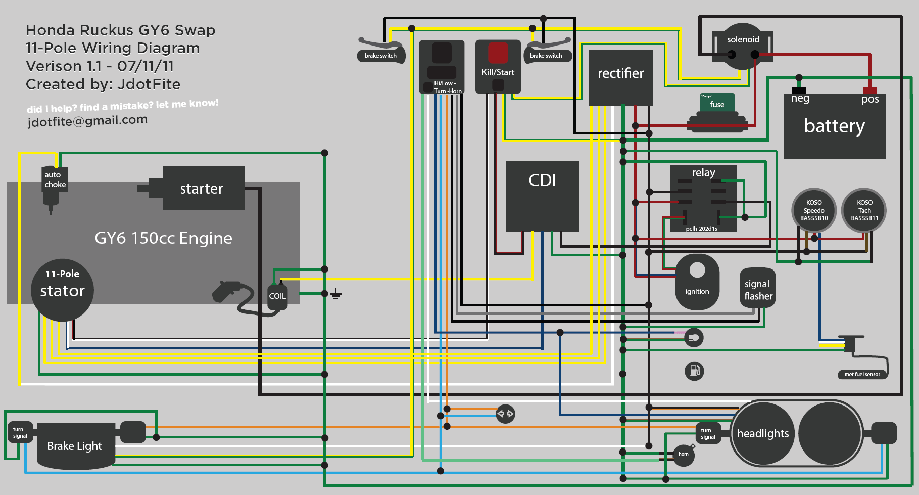
Gy6 4 Pin Cdi Wiring Diagram Wiring Diagram

12v 3 Phase Motorcycle Regulator/rectifier Circuit Wiring

3 Wire Rectifier Regulator Wiring Diagram Wiring Forums

4 Pin Regulator Rectifier Wiring Diagram easywiring

10+ Motorcycle Without Battery Basic Wire Diagram

Image result for 12v rectifier regulator wiring diagram

Rick’s Rectifier Wiring
Re Is there a cheep and reliable regulator rectifier
Rectifier Wiring Diagram honda cb750k ltd 1979 usa spec


Voltage Regulator 4 Pin Regulator Rectifier Wiring Diagram

4 Pin Regulator Rectifier Wiring Diagram easywiring
29 4 Pin Regulator Rectifier Wiring Diagram Wiring

Gy6 4 Pin Cdi Wiring Diagram Wiring Diagram
Understanding Motorcycle Voltage Regulator Wiring
4 Wire Voltage Regulator Diagram Car Wiring Diagram

الترحال بحار مرض 5 pin regulator rectifier wiring diagram

Yamaha Rectifier Regulator Wiring Diagram Wiring Diagram

BATTERY SOLUTIONS December 2012