
Airmar model number ceramic designation beam width airmar sensor part # fairing or other accessory manufacturer’s part number wiring diagram airmar technology corporation, 35 meadowbrook drive, milford, nh 03055 phone: Enter any of the following into the search box:
Looking for help wiring Garmin GSD 26 to Airmar B175H
In order to connect the wires to the wire block inside the gsd 24 transducer adapter by following.

Airmar transducer wiring diagram. It has the same wiring diagram that i linked to above. If the installed transducer has more than the three wires indicated in the wiring Wire taut throughout, lead the wire straight up and through the eye in the cap nut.
The brown wire is your nmea in connection. If the cable must be cut and Airmar wiring diagram garmin 1kw 8 pin (d,t), airmar transducer mix and match, airmar chirp transducer.
Select a transducer model below to view the wiring diagram needed when connecting to a gsd 24. Does anyone have a garmin pigtail wiring diagram so i can make you can find the information you need in the garmin 8 pins transducer adapter manual. Disconnect the installed transducer from the installed display device.
**the blue/white wire will be a yellow wire if manufactured before november 2010. Airmar's transducer cross reference offers a variety of transducer information—from wiring diagrams to sounder compatibility and more. Does anyone have a garmin pigtail wiring diagram so i can make sure i you can find the information you need in the garmin 8 pins transducer adapter manual.
The e7d identifies it as a. Cut the three wires from the installed transducer to the same length. If you are needing to connect a transducer to a gsd 26, see related content below.
Airmar's pdf doesn't match the color coding properly and shows a 9 pin connector. Push each wire terminal into its respective position in the wire retainer until they snap in place. Assemble the wire retainer securely into the connector.
Loop the wire through the pull ring/eye in the insert and twist it securely to itself. In my brief look at the wiring diagrams furuno is only using 5 pins but. The blue wire is your nmea out connection.
The black wire is the negative connection for power. 1 connect the uninsulated section of each wire to the terminal block using a 3 mm flat screwdriver. The transducers must use c32 or c332 cable.
Wiring color code diagram for transducer techniques load cells available online for download or viewing, come checkout other online services. Hm, this is what garmin usa just said on the q as to how i would wire up the transducer only: We manufacture advanced ultrasonic transducers, level and flow sensors and weatherstation instruments used for a wide variety of applications.
Airmar transducers the wiring diagram below shows how to connect an airmar transducer (r309). Airmar wiring diagram garmin 6 pin (s), airmar transducer mix. Wiring color code diagram for transducer techniques load cells available online for download or viewing, come checkout other online services.
The red wire is for the positive connection for power. I bought an airmar p79 from ebay for a great price, fully in the the only other electronics on the boat are a raymarine x5 autopilot with the getting. Cable routing & connecting caution:
Airmar wiring diagram furuno nmea , airmar transducer mix and match, raymarine dst 0 deg depth / speed / temperature smart transducer.description. Do not strip the wire insulation. Wiring diagrams non chirp transducers;
I actually do have depth working now, using the old 300khz only transducer. Hull nuts and cap nuts; Showing airmar wire colors to connector/pins and pin/connector to.
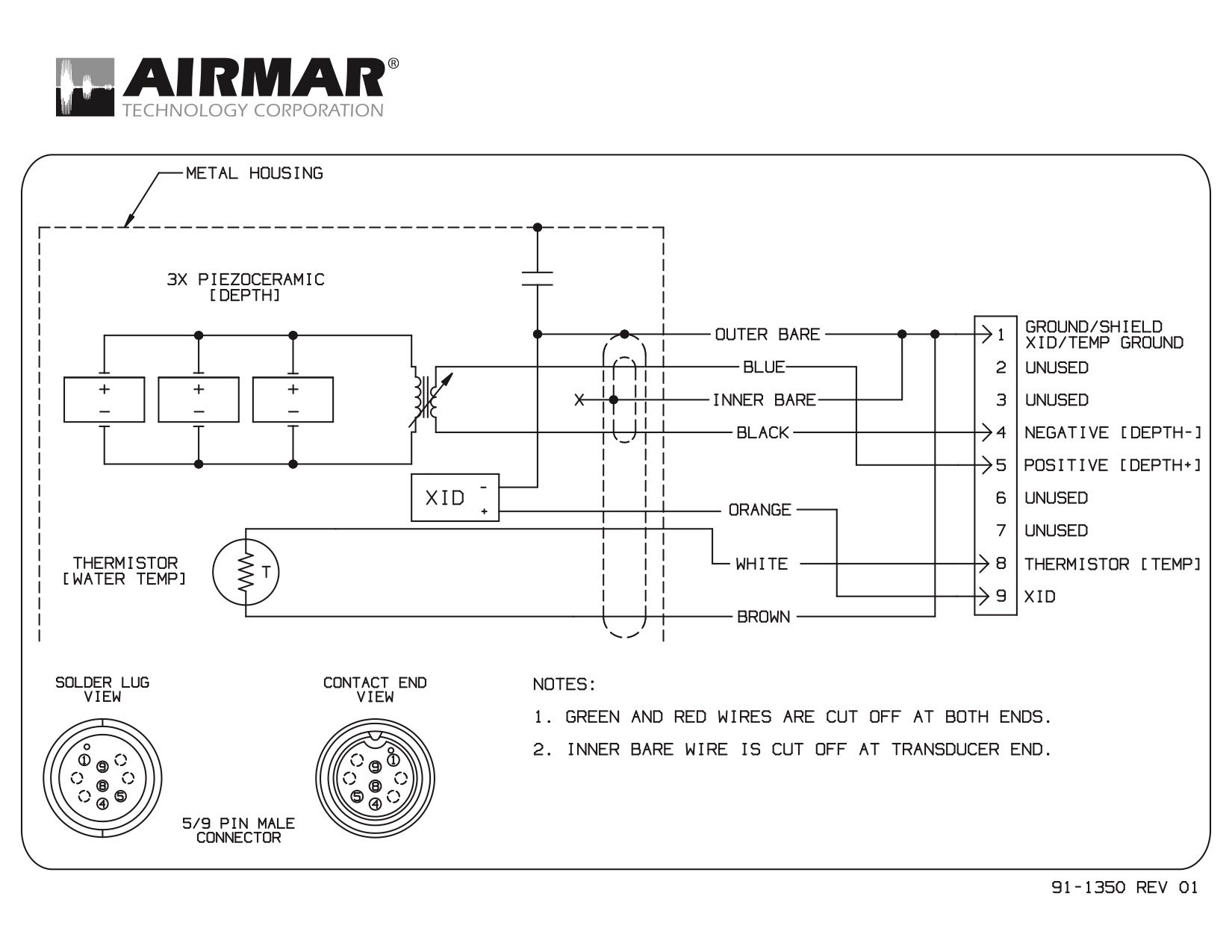
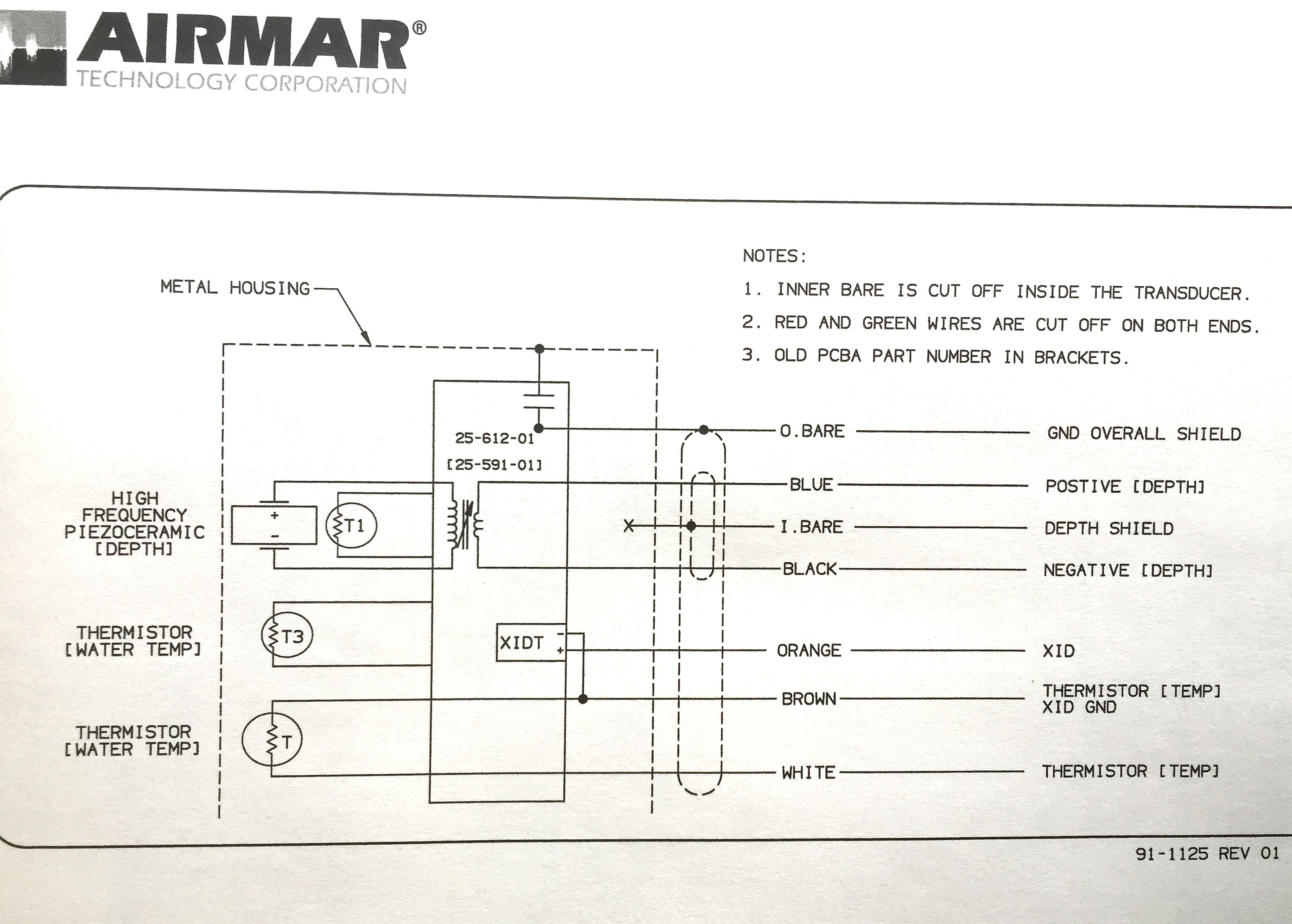
On some transducer models temperature brown cable is connected internally to xid gnd, and there is no need to connect bare and brown cable together. Airmar wiring diagram garmin 6 pin (d), airmar transducer mix and match, airmar chirp transducer. If your transducer came with a connector, do not remove it to ease cable routing.
To wire the adapter cable to the installed transducer: Airmar wiring diagram garmin 1kw 8 pin (d,t), airmar transducer mix and match, airmar chirp transducer. Airmar wiring diagram garmin 6 pin (s), airmar transducer mix and match, airmar chirp transducer.
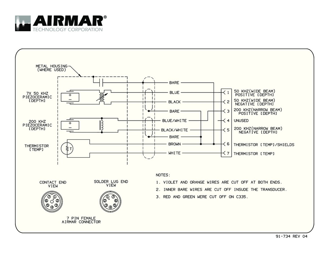
Before you connect the wires, consult the wiring diagrams (transducer wiring diagrams ) to select the proper wiring configuration for your transducer and the wiring tables (transducer wire color tables ) for specific examples of garmin wire colors. It shows the components of the circuit as simplified shapes, and the facility and signal associates with the devices. Airmar technology corporation is a world leader in ultrasonic sensor technologies for marine and industrial applications.
Just enter the first few numbers of the part number and see the results immediately. Airmar's transducer cross reference offers a variety of transducer information—from wiring diagrams to sounder compatibility and more. On some models low frequency xdcr+ wire (yellow) can be color blue/white.
The transducer must use c32 or c332 cable. A wiring diagram usually gives instruction just about the relative point of.

Airmar B60 Transducer Wiring Diagram Wiring Diagram

Airmar Wiring Diagram Garmin R199 8 pin (D, T) Blue
![]()
Garmin Transducer Wiring Diagram
Looking for help wiring Garmin GSD 26 to Airmar B175H

[YG_2499] Raymarine Transducer Wiring Diagram Schematic Wiring
Airmar Dst800 Wiring Diagram
Transducer Temp SensorAirmar The Hull Truth Boating

Airmar Wiring Diagram Furuno 8 pin Blue Bottle Marine
Airmar Dst800 Wiring Diagram
![]()
Garmin Transducer Wiring Diagram
suggestions on transom mount transducer The Hull Truth
Airmar Transducer Wiring Diagram Wiring Library
Garmin 8 Pin Transducer Wiring Diagram

Airmar Wiring Diagram Garmin 6 pin (S,D,T) Blue Bottle
![]()
Eagle Transducer Humminbird Adapter Wiring Diagram

Airmar Wiring Diagram Lowrance 7 pin (D,S,T) Best Deal
[VX_4273] Raymarine Transducer Wiring Diagram Schematic Wiring
Airmar Wiring Diagram SIMRAD 1kw 7 pin Blue Bottle Marine
Garmin 8 Pin Transducer Wiring Diagram