
Connect wire from ignition switch to the positive. However, it doesn’t imply connection between the cables.
Autometer Egt Gauge Wiring Diagram
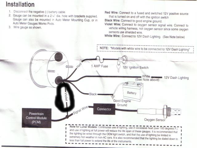
Gauge can be mounted in a 21⁄ 16” dia.
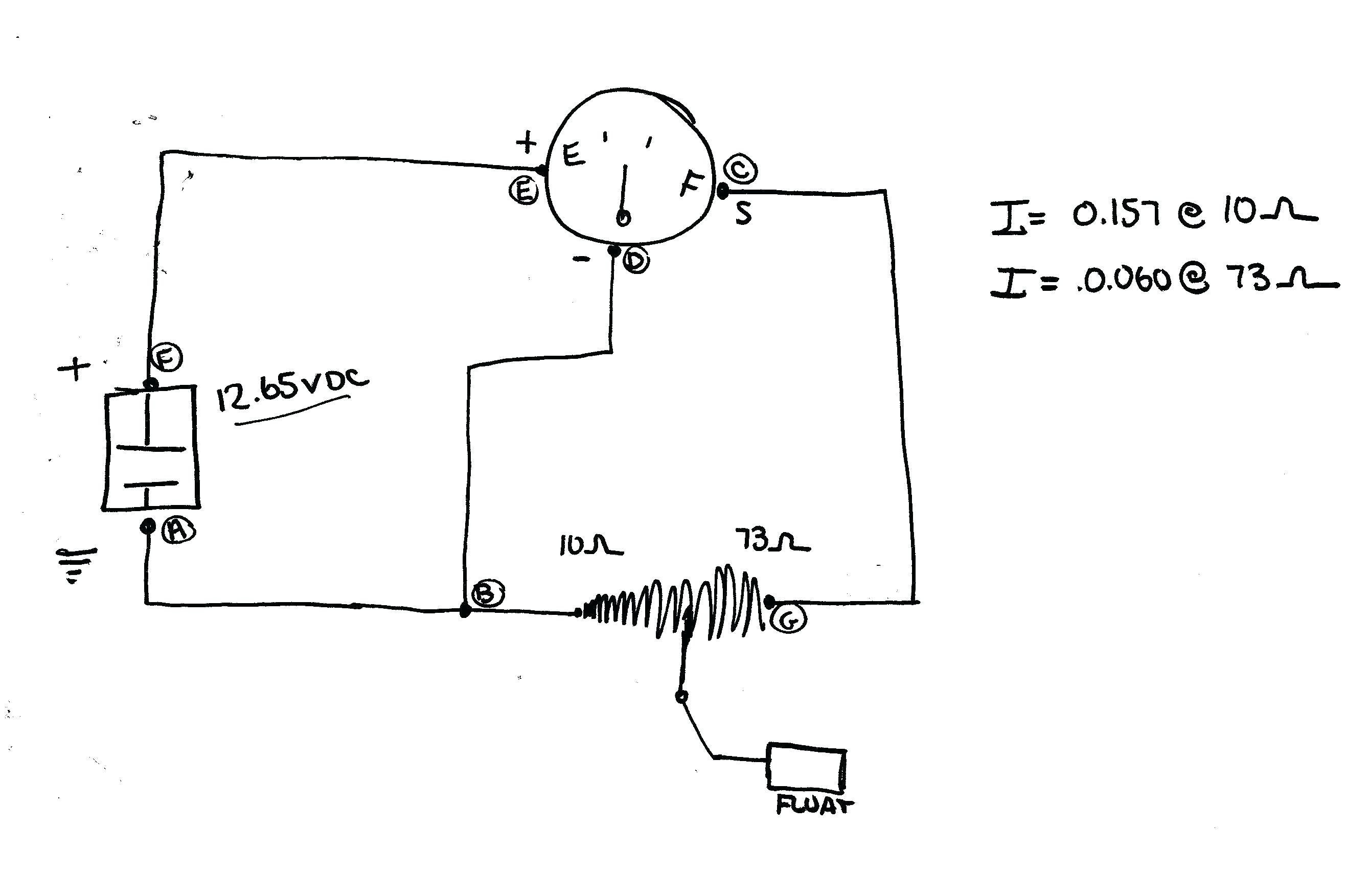
Autometer air fuel gauge wiring diagram. Autometer air fuel gauge wiring diagram. Connect to oxygen sensor signal wire. S = this connects to the sending unit in the fuel tank.
Occasionally, the wires will cross. As stated earlier, the traces in a autometer gauge wiring diagram signifies wires. Connect one end to terminal post on fuel level sender and the opposite end to the sender (s) terminal spade on back of gauge.
Attach one length of wire to the positive i (+) terminal on back of gauge and opposite end The autometer wiring for the fuel gage is pretty simple, ground, signal, 12v+, and that's it. Connect to oxygen sensor signal wire.
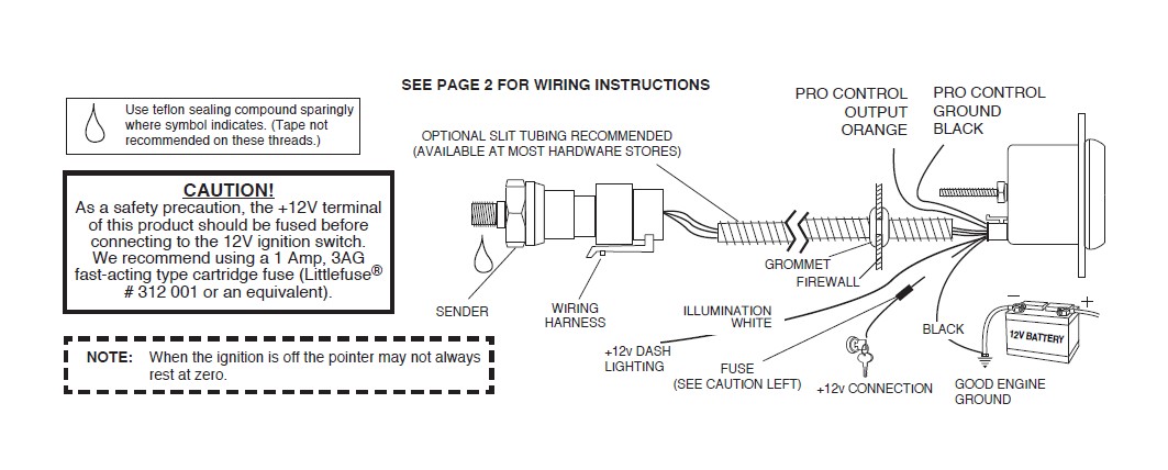
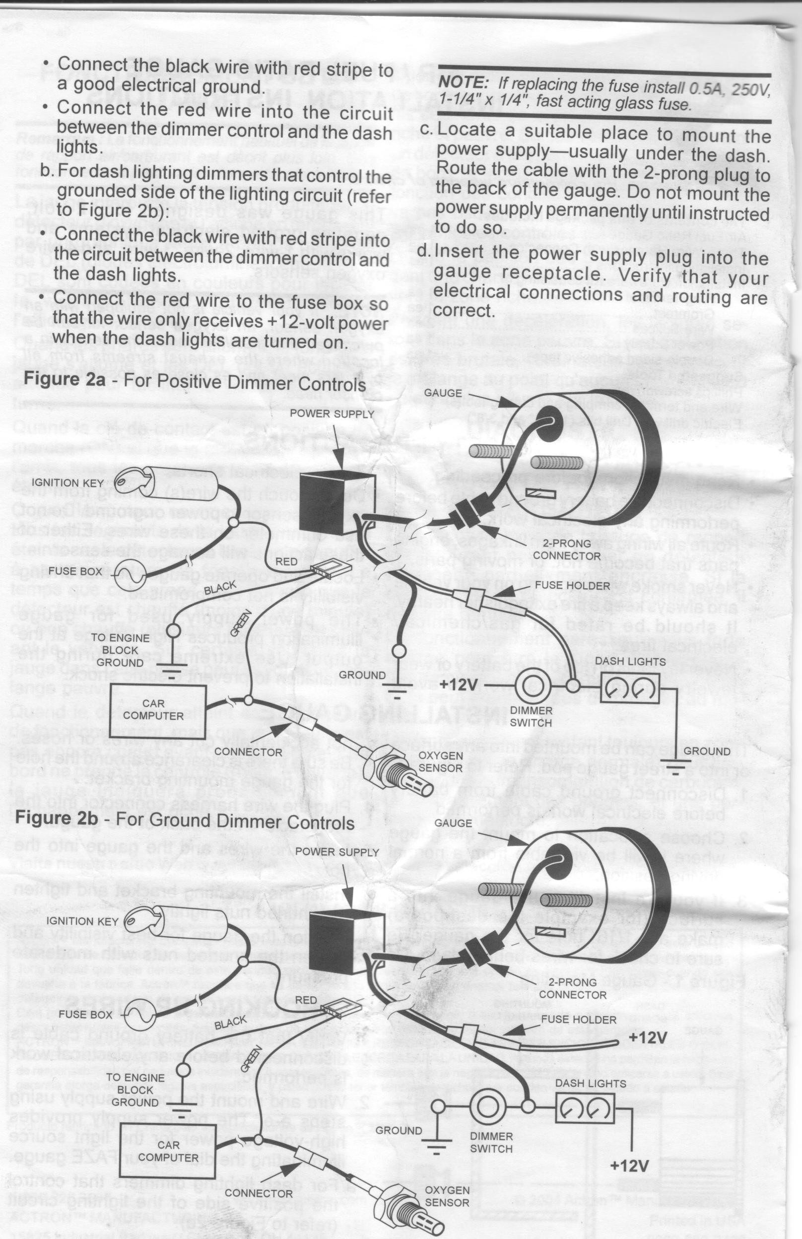
Digital temperature controller wiring diagram. Connect to a fused and switched 12v positive source that is turned on and off with the ignition switch black wire: Note that the voltages from the o2 sensor are very low, so take extra care in taping the signal wire and make a high quality connection.
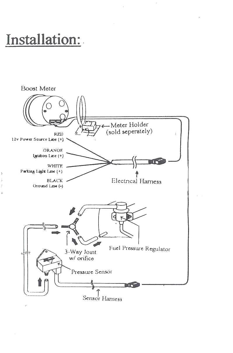
Autometer electric fuel pressure gauge wiring diagram. Connect to vehicle wiring harness, not oxygen sensor since some oxygen Back of gauge using adapter, ferrule, and compression nut as shown in diagram above.
Gauge can also be mounted in auto meter mounting cup, or in auto meter gauge works pods. So i can monitor the o2 sensor. Insert the wires through the hole in the dash and route them into the engine bay.
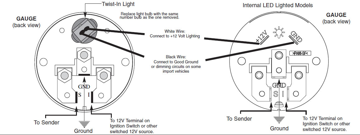
Looking at the rear of the gauge, you will have 3 terminals labeled s, i, & gnd. Connect to good engine ground. 12v ignition switch good engine ground
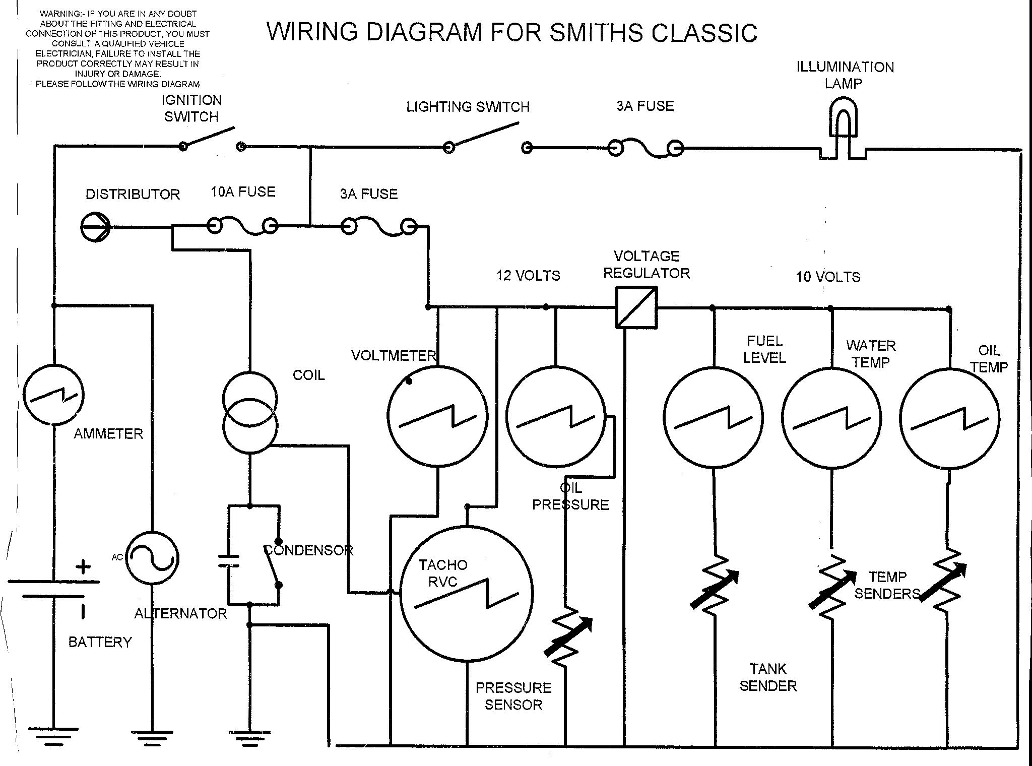
Analog wideband air/fuel ratio gauge figure 1. Using 18 gage wire, route one length through firewall. It contains directions and diagrams for various varieties of wiring strategies along with other things like lights, windows, etc.
Suzuki outboard gauge wiring diagram. Rosemount 644 temperature transmitter wiring diagram. Autometer electric fuel pressure gauge wiring diagram.
Press the gauge into the mounting kit. If a new hole is drilled in the firewall a grommet is recommended. If a new hole is drilled in the firewall a grommet is recommended.
I refuse to spend $100 for a black autometer unit so it matches the other gauges. Connect to good engine ground. I would make sure that you have a good ground first off.
Check your bentley wiring diagrams to find the best place to connect to the o2 wiring harness. Components available on your auto meter wideband air fuel gauge. 18 gage, wire from fuel tank to gauge.
Connect to good engine ground. However, it does not mean connection between the wires. Connect to dash lighting dimmer control.
**(see sending unit wiring section) i = supply 12v, key on power to this terminal. Twist these two wires together and cover them with a layer of electrical tape. This is whati gathered for my intellitronix gauge.
Connect ground wire from ground post on gauge to suitable chassis ground. Universal gauge wire harness for installing auto meter electric speedometer tachometer and short sweep electric oil pressure water temperature fuel level and volt meter gauges. Air fuel ratio gauge wiring diagram have a graphic from the other.
Auto meter gauge works pods. If you would like to put the gauge into the dash, cut a hole in the dash the same size as your air fuel gauge using a rotary tool. As stated earlier, the traces in a autometer gauge wiring diagram signifies wires.
It contains directions and diagrams for various varieties of wiring strategies along with other things like lights, windows, etc. Injunction of two wires is generally indicated by black dot on the junction of 2 lines. Air fuel ratio gauge wiring diagram it also will include a picture of a sort that could be seen in the gallery of air fuel ratio gauge wiring diagram.
Connect to a fused and switched 12v positive source that is turned on and off with the ignition switch. Gauge can also be mounted in auto meter mounting cup or in auto meter gauge works pods. Injunction of two wires is usually indicated by black dot on the intersection of 2 lines.
An initial look at a circuit layout may be complex but if you could check out a. There’ll be main lines that are represented by l1, l2, l3, and so on. Brown wire (heater override for applications that provide less than 12.5 volts with engine running):
Step 1 use the wiring diagram and test light or multi meter to locate the positive wire from the alternator to the fuse block. Ok, i am assuming the feul pump was making a funny noise because it was sucking air. Connect the purple sender wire to the fuel level sender.
It works fine, the center lights up white and the leds dim when the dash lights are on. Autometer volt gauge wiring diagram. Gauge can also be mounted in auto meter mounting cup, or in auto meter gauges works pods.
Sometimes, the cables will cross. A wiring diagram is a simplified conventional photographic representation of an electrical circuit. You may use 18g or 20g stranded wire for all fuel level gauge wiring.
Install Electrical Tachometer bunnythepiratebay

AEM 304900 Wideband AFR Gauge Ford Mustang Forum
32 Autometer Fuel Gauge Wiring Diagram Wiring Diagram

29 Autometer Pro Comp 2 Wiring Diagram Wiring Database 2020

Aem Air Fuel Gauge Wiring Diagram Wiring Diagram And
Autometer Wideband Wiring Diagram

How to Install Auto Meter Factory Match Fuel Pressure

Autometer Air Fuel Gauge Wiring Diagram 29
29 Autometer Pro Comp 2 Wiring Diagram Wiring Database 2020

Autometer Air Fuel Gauge Wiring Diagram THEINSTRUMENT


Air Fuel Ratio Gauge Wiring Diagram Wiring Diagram And
Wiring Diagrams Universal Fuel Gauge Wiring Diagram
Please Help With Air/Fuel Gauge Install
gauges???

Air Fuel Ratio Gauge Wiring Diagram

Aem Air Fuel Ratio Gauge Wiring Diagram
Autometer Gauge Wiring Diagram Wiring Diagram
Autometer Gauge Wiring Diagram Wiring Diagram

Glowshift Gauges Wiring Diagram Wiring Diagram And