Solved would the code po113 iat sensor have your car fixya. Accelerator pedal position sensor wiring diagram wiring diagram is a simplified satisfactory pictorial representation of an electrical circuit it shows the components of the circuit as simplified shapes and the skill and signal links amongst the devices.
Crank Sensor Wiring Diagram Style Guru Fashion, Glitz
This next crank sensor testing technique also uses the diagnostic scan tool.

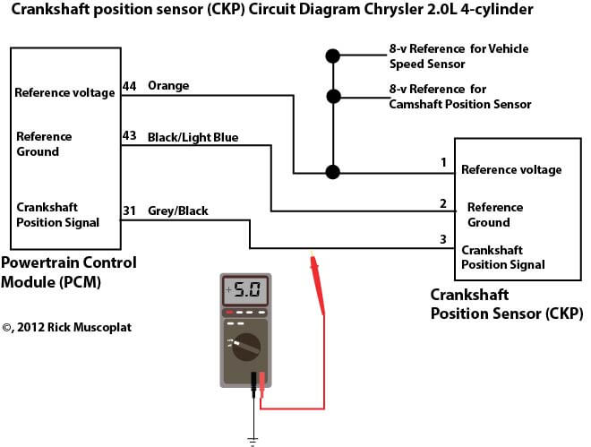
Crank sensor wiring diagram. Attach one end of the multimeter to each wiring lead of the sensor. The following tutorial will help you to test the crankshaft position (ckp) sensor: 2l chrysler crankshaft sensor wiring diagram test 2.0 chrysler crankshaft sensor.
If the specified value is obtained, check the wiring for continuity or short between crankshaft position sensor and ecm, using a wiring diagram. There are two most common types of crankshaft position sensors that are used commonly in the car. Wiring diagram courtesy of alldata current phaser description:
18.11.2015 · if spikes or glitches are observed, carefully wiggle the wiring harness and connector for the sensor in question to try and determine whether the problem is a loose connection or a defective. Any help would be great! Each component ought to be placed and linked to different parts in particular way.
Wiring diagram crankshaft position sensor bmw e90 eccentric shaft position sensor pelican parts. You can also find other images like wiring diagram, parts diagram, replacement parts, electrical diagram, repair manuals, engine diagram, engine scheme, wiring harness, fuse box,. Does anyone have a wiring diagram with the correct colors of wires and correctly labeled sensor plug where each colored wire is supposed to go?
Classic whaler boston whaler reference wire color code. A wiring diagram makes it easier to check for shorts to ground or power and of course, check for continuity between the crank sensor. The benefits of the vane type cam phaser are a faster response time and a lighter, more compact design.
Cam sensors crank sensor camshafts. I had some problems with the crankshaft position sensor connector, with a purple and yellow wire that has light green on it around the plug is. Connect a vag 1598/19 test box to the ecm harness connector.
Turn the ignition key to the on position. Related cmp sensor trouble codes: Honda recommends replacing the wiring harness and crankshaft sensor with updated parts that correct the.
Crank sensor test (4.8l, 5.3l, 6.0l) no spark no start tests (at: We collect plenty of pictures about 2003 dodge ram 2500 57 hemi throttle body wiring diagram. This information on testing the 2l chrysler crankshaft sensor pertains to.
14 flexplate jet 5 7 starters 0170 000 starter. This sensor measures the pressure of the engine oil and relays this data to the pcm. Use shielded/grounded cable that is supplied for wiring crankshaft and camshaft signals.
A wiring diagram makes it easier to check for shorts to ground or power and of course check for continuity between the crank sensor and the pcm. The wiring diagram of the camshaft position sensor is different according to the year, make, and model. In this powerful guide, we will be more general than specific.
On 2002 gmc sonoma 4.3 crank sensor wiring diagram. Brn/yel wire feeds chassis ground. The vane type vvt system utilizes the camshaft
Be the first to answer jul 08, 2014 • 2008 chevrolet colorado 2wd. Keep sensor wiring away from high voltage or “noisy/dirty” components and wiring, especially secondary ignition wiring, ignition boxes and associated wiring. 1993 1995 fuel pump wiring diagram jeep 4 0l.
Your meter should read between 5 and 13 volts. Search fixya my gmc sonoma will start but will stay running gmc sonoma l v6 changed everything in the fuel and ignition system except for the why is the engien dying. Using the hayne's manual diagnostic flow chart, i have not replaced the ignition pickup coil (camshaft position sensor).
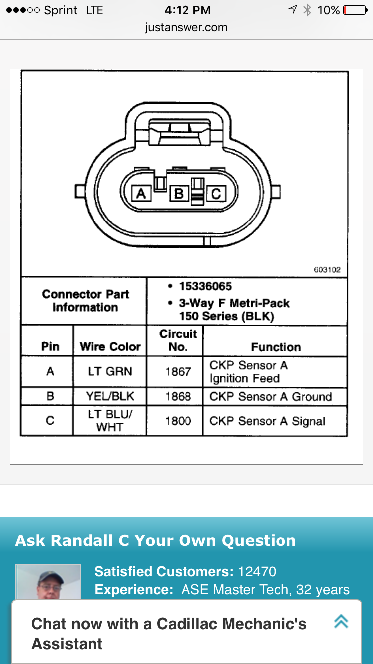
2 & 3 wire crank sensor wiring diagram (with pictures) the crankshaft position sensor is an electronic sensor that measures the position of the crankshaft. Consult your vehicle repair manual for the reference voltage value for your particular model. The illlustrations and info in this page apply only to 1996, 1997, 1998 dodge ram pickups, vans, and dakota with a 3.9l, 5.2l or 5.9l gasoline engine (that use the 3 connector pcm).
Maf sensor wiring diagram 1997 1999 ford 4 6l 5 4l. Blu wire carries crank signal to pcm. Diagram chevy 5 7 vortec crank sensor wiring diagram full version.
I mean, i am giving you a general idea of. Crankshaft position sensor wiring diagram. Crankshaft position sensor wiring diagram.
Discussion starter · #1 · apr 8, 2015. You may need to check the wiring diagram for your particular model, if the ckp sensor uses wires of different color to identify the ground, power and signal wires. How to rewire crank sensor on chevy colorado need color coded wiring diagram for the crank sensor plug , my plug was cut off ,i need to rewire it to the harness.
Crankshaft position sensor wire color id and description. Crankshaft sensor diagnosis with an ohmmeter. Hall effect crankshaft position sensor
Properly solder and heat shrink any wire connections. Yel/blk wire feeds 12 volts from pgm relay. This tutorial will help you test the ignition coil, ignition module, and the crankshaft position sensor:
Camshaft position sensor wiring diagram. P honda accord description the crankshaft position sensor also known as the crank position sensor is an electronic device used in an engine to record the rate at. Crankshaft position sensor wiring harness diagram bmw e90 e91 e92 e93if you need to find the crankshaft position sensor wiring harness and the wire order for.

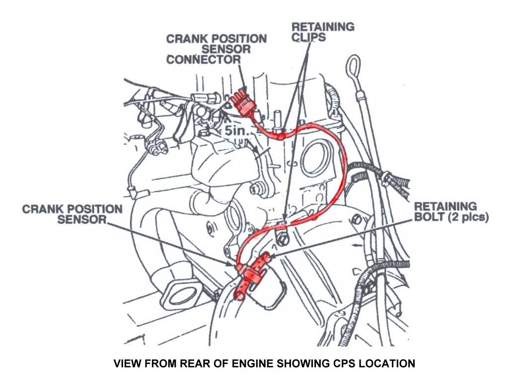
Wiring for upper crankshaft position sensor connector

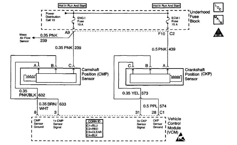
Delphi Crankshaft And Camshaft Position Sensor Wiring Diagram
24x SBC conversion Wiring for sensors

Delphi Crankshaft And Camshaft Position Sensor Wiring Diagram

95 nissan cranck over wont start no pwer to cranck sensor

Delphi Crankshaft And Camshaft Position Sensor Wiring Diagram
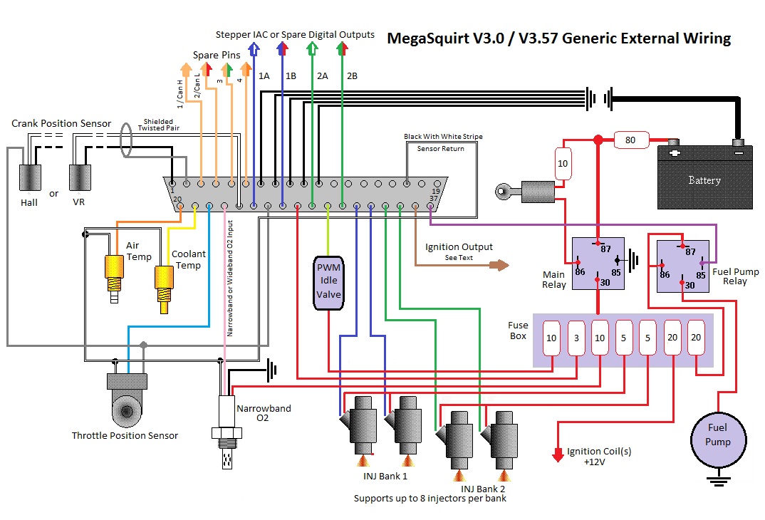
MS3 crank position sensor wiring Miata Turbo Forum
I need the wiring diag for a 01 jetta with a vr6 the crank
Crankshaft position sensor connectors GM Forum Buick
2L Chrysler crankshaft sensor wiring diagram — Ricks Free

Crankshaft position sensor configuration and conditioning
Repair Guides Electronic Engine Controls Crankshaft


2002 Gmc Sonoma 4.3 Crank Sensor Wiring Diagram
Crank Sensor Wiring Diagram Wiring Diagram and Schematic
Repair Guides


Q26k [DIAGRAM] 2003 Dodge Dakota 4 7 Crank Sensor Wiring

2002 Gmc Sonoma 4.3 Crank Sensor Wiring Diagram
Cam Sensor Wiring Diagram
Where is the crankshaft sensor located on a 2003 Town and