
Note that injector wiring specifics are in the injectors & fuel supply section. You connect half the injectors on one bank (injector 1) and half on the other (injector 2).
Throttle Body Fuel Injection Systems Diagram Wiring Forums
If you are using the relay board, use these diagrams.

Fast fuel injection wiring diagram. Cold start valve) are powered during starter cranking, which also powers an internal heating element on the bimetallic element for a combination of time and sensor (engine block) temperature dependent operation, to. As can be seen in the '73 1800es fuel injection wiring diagram above, this component as well as the cold start injector (also: The fitech go efi system is the industry's most.
External wiring schematic (this wiring diagram is for those creating their own harness for a v2.2 main board. This wire should be as short as possible and be solidly attached to the. According to earlier, the traces in a fuel injector wiring diagram signifies wires.
The other pin on each connector is supplied with 12 volts through the main relay (see diagram) and the injector pins ground the injectors to 'fire' them and squirt fuel. Wiring diagram will come with a number of easy to stick to wiring diagram directions. When rpm reaches this value, the injectors will be disabled.
Fast® classic to xfi™ adapter harness. Mount the o2sensor in the upper half of the exhaust tubing, with the angle “x”, shown above, being greater than 10°. Fast® xfi™ 4 cylinder injector harness part #301207.
These directions will likely be easy to comprehend and use. It is meant to aid all of the common consumer in developing a suitable program. Fitech fuel injection tm instruction manual for the following go efi systems , , , , , & this quick start manual is designed to get you up and.
Our recommendation is to use a 1n4001 diode. Holley has been the undisputed leader in fuel systems for over 100 years. Weld the threaded boss into the 7/8” hole.
This quick start manual is designed to get you up and running with the go efi system base kit and either the 50004 force fuel or the 50001 inline fuel delivery kit. The manual and wiring diagrams for the xfi 2.0 are built into their tuning software package. The fuel rails shown in the list are edelbrock parts designed to fit a victor efi manifold.
These connect to one pin on each connector. Figure 3indicates that the sensor can be mounted on either side of the exhaust tubing. 1 8 npt port for installation holley fuel pressure regulators have an 1 8 npt port.
Injunction of 2 wires is usually indicated by black dot at the intersection of two lines. Fast e6 ignition box wiring diagram fast e6 cd ignition box w/ built in rev limiter, black fas this e6 is supplied with a weatherpak connector and harness to help route the wiring. Fast wiring diagrams xfi 2 0 infinitybox instructions efi the oohs aahs and what for installation manual em atomic sniper system nitrous oxide ez fuel injection installing s 1 pdf man factory five forums fitech go sensors pressure regulator 30 70 psi adj v3 micro controller introduction between turbo sw bosch d jet notes electronic sites holley.
But, it doesn’t mean connection between the wires. Fast™ wiring harnesses are labeled on each of the connectors to simplify this connects to the can link connection on your fast™ xfi™ main harness. Wiring manual diagrams 199r10555 hp efi and dominator efi systems.
It is important that you install the diodes that are shown in the diagram. Apr 27, · thoughts on fitech efi the distributor wires connect into the crank sensor wires shown on the wiring diagram. Also available are a remote mounted iac kit and an adapter for installing an early gm iac on a ford throttle body.
Drill a 7/8” hole in the location picked for the sensor. Do not use solid core ignition wires. • use fuel injection rated fuel line, filters, pump, etc.
Fast e6 ignition box wiring diagram. Here is a picture gallery about fast xfi 20 wiring diagram complete with the description of the image please find the image you need. Occasionally, the wires will cross.
You can download that by clicking this link. The following wiring diagram shows all of the connections between the fast xfi 2.0 and the infinitybox system. If you purchased a kit or kit 55 master kit, or one of the fast™ fuel kits, then you have everything cd ignition box will receive the ecu's ignition output signal and fire the coil.
The harness is wired for eight traditional “minitimer” style injectors. Fast xfi 2.0 wiring diagram. If you are using a v3 main board, use this wiring diagram.) external wiring with a v3.0 main board

Fast Xfi 2.0 Wiring Diagram
Fast Fuel Injection Wiring Diagram Wiring Diagram

Fast Xfi 2.0 Wiring Diagram Wiring Diagram And Schematic

Wiring Diagram Holley Efi

Throttle Body Fuel Injection Systems Diagram Wiring Forums
Wiring diagram for under hood mostly fuel injection

Fast Ez Efi 1 0 Wiring Diagram Wiring Diagram and Schematic
F.A.S.T. EZ EFI Kit Install EFI It’s Not Just For Your

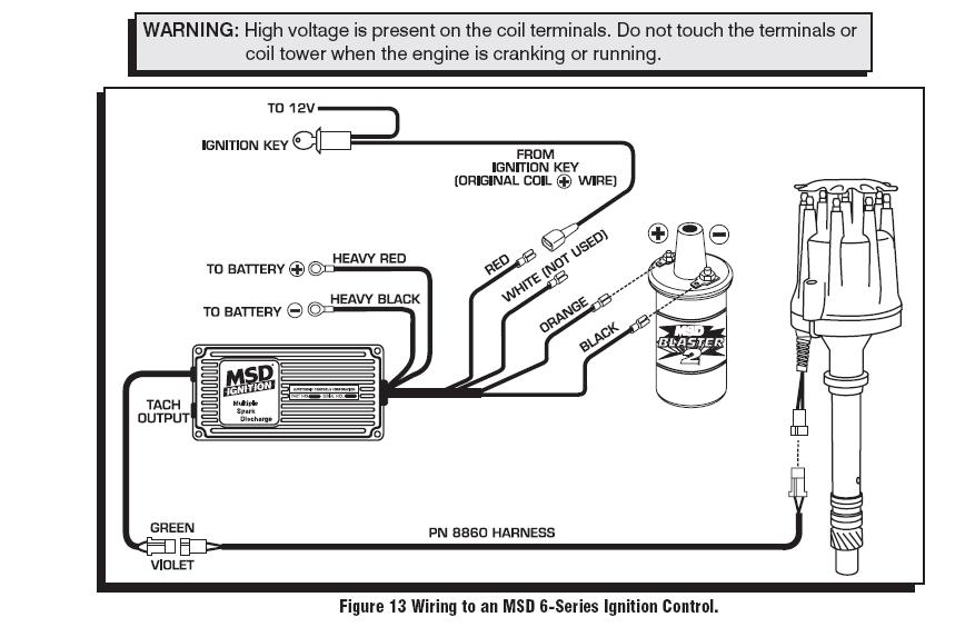
Fast E6 Ignition Box Wiring Diagram

EFI System Electronic And Mechanic

Fast Fuel Injection Wiring Diagram Wiring Diagram

EZEFI Pinout WiringDiagram EZ EFI 2.0 to run a RamJet

Wiring Diagram Holley Efi
SR50 Ditech 04 Wiring Diagram Fuel Injection Ignition


Throttle Body Fuel Injection Systems Diagram Wiring Forums

Wiring Diagram Holley Efi

FAST Wiring Diagrams
Fast Xfi Wiring Diagram Wiring Diagram Pictures


Fuel Injection Wiring Diagram 2003 Wiring Diagram