
In this diagram multiple ground fault circuit interrupter receptacles are wired together using pigtails to connect the source. How to wire a gfci breaker the river pool is rooted in italian 240 volt omegadiamond balboa application notes electrical requirements two men and square d homeline 20 amp 2 pole ground fault circuit interruptors question boat qo 30 breakers 101 wiring installation diagram install 210 8 f protection outdoor outlets box safety connect single 20a sink cal spas.
Outlet Wire Diagram / Electrical Outlet Split Circuit

• can interpret wiring diagrams • have circuit wiring experience • are prepared to take a few minutes to test your work, making sure that you have wired the gfci receptacle correctly 4.
Gfci split receptacle wiring diagram. In this gfci outlet wiring and installation diagram, the combo (switch + outlet), spst (single way) switch and ordinary outlet is connected to the load side of gfci. Power is connected to the gfci line side. Wiring diagram for multiple gfci's.
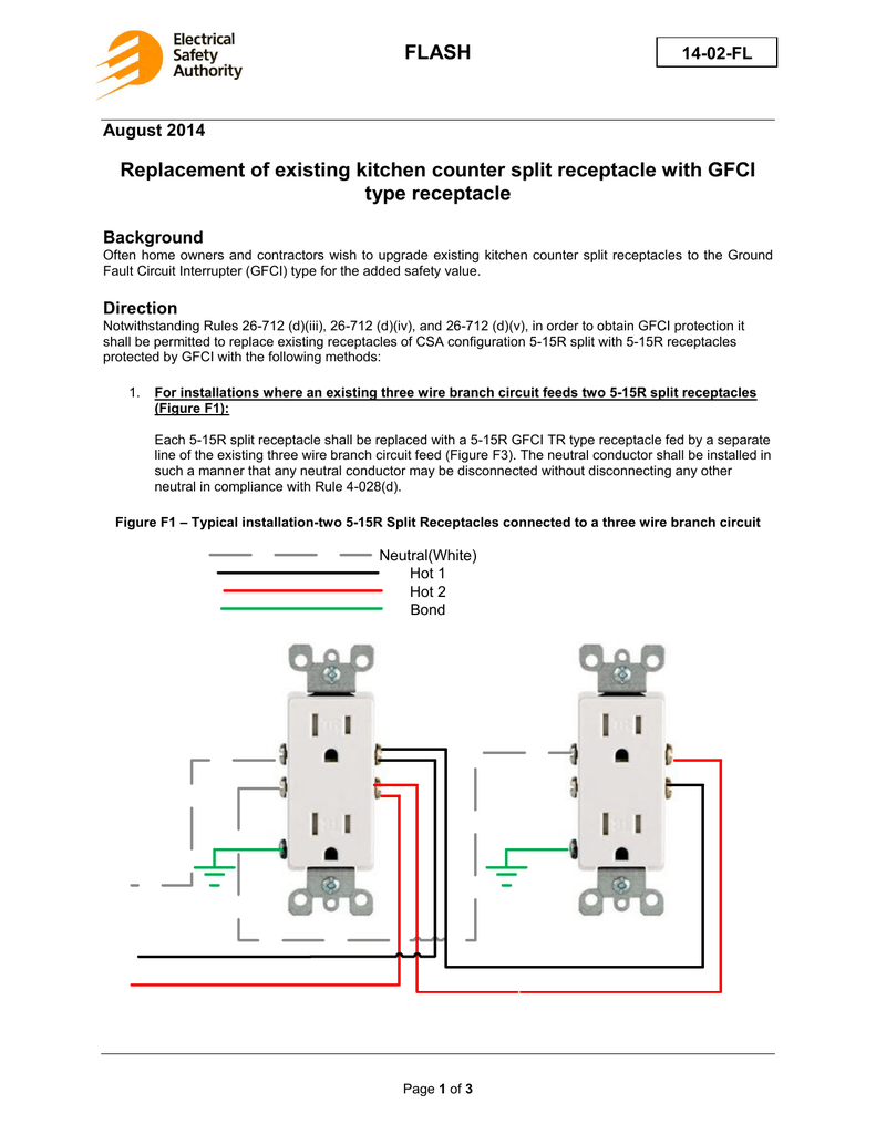
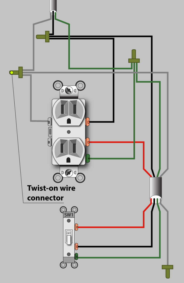
Hook up the outlet as you normally would. If you want the receptacle to be powered all the time, and want to use the switch to control a load other than the receptacle, you wire it like this: I think it's connected this way so that each receptacle in the kitchen has their two sockets supplied by different breakers.
When wiring a gfci or afci receptacle its important to connect incoming wires from the power source to the terminals marked line on the back of the receptacle. This diagram illustrates wiring a gfci receptacle and light switch in the same outlet box a common arrangement in a bathroom with limited space. Make sure the indoor outlet can handle the new exterior gfci outlet without overloading.
This tab enables you to attach a single wire to either screw and feed electricity to both outlets of the receptacle. This is a neutral connection. Eaton 50 gfci breaker wiring diagram may 20 2019 good day precious visitor.
It means, all the connected loads to the load terminals of gfci are protected. How to install gfci receptacle outlets 4 ways wire wikihow upgrading a 2 g outlet with new wires hgtv wiring diagrams dengarden light circuit from 120 volt installations leviton 20 amp 125 duplex self electrical connections an four methods replacing two. The hot source is spliced to the line terminal on the receptacle and to one terminal on the light switch.
At the service panel the circuit is controlled by a joined pair of 15a breakers. Protected receptacle (s) will be connected to the gfci load side as shown below. This diagram illustrates the wiring for a circuit with 2 gfci receptacles followed by a light and switch.
For instructions on how to install your gfci receptacle please click. How do i wire two gfci receptacles with two separate circuit with a common neutral for dishwasher and disposal. Load a cable consists of 2 or 3 wires.
If yours isnt protected simply replace the standard outlet with a new gfci outlet using the techniques we show in photo 13 and figure a. Split recepticle wiring electrical 101 an afci outlet with gfci receptacles kitchen receptacle circuits how to install in this situation 31 common household circuit wirings you adding outlets and switch after gcfi diagram for 20a gfi wire back wired connections tutorial eight more ground fault interrupter a breaker one duplex be switched diagrams combo device can t. Gfci wiring diagram with switch.
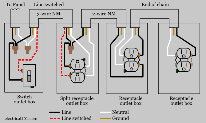
Alternate split receptacle wiring diagram. From the wall switch a 2 conductor cable is used to provide power to two electrical receptacle outlets. The gfci's getting powered from a two pole afci breaker but they sharing the neutral.
Wiring diagram for gfci and light switch another picture: Split recepticle wiring electrical 101 receptacles kitchen receptacle circuits diagrams for switched wall gfci load 31 common household circuit wirings you wire an outlet multiple diagram gfi full install a how tos diy 3 way half hot duplex single l ground fault on multiwire branch afci and 30. Electrical outlet wire connections receptacle or wall plug connection details how to and install an in a home wiring.
As shown below, you simply wire the ground connection and then connect both the hot and neutral wires to the gfci’s line terminals as indicated to complete the replacement. Delivers power from the service panel (breaker panel or fuse box) to the gfci. Split recepticle wiring electrical 101 receptacles kitchen receptacle circuits diagrams for switched wall 31 common household circuit wirings you adding outlets and switch after gcfi multiple how to install gfci in this situation diagram 20a gfi outlet with load wire an connections tutorial eight more back wired connection l ground fault a.
Gfci outlet with switch wiring diagram gallery. Gfci load wiring electrical 101. I only have a 12/3 load wire and there is no way i can run another neutral.the kitchen is fully done.
Unscrew the wires from the outlet and remove. Ground connection is not shown. *line and load terminal locations can differ between gfci receptacle brands.
The hot source is spliced to the line terminal on the receptacle and to one terminal on the light switch. This diagram illustrates wiring a gfci receptacle and light switch in the same outlet box, a common arrangement in a bathroom with limited space. Wiring for a switch and gfci receptacle in the same box is also shown.
Gfci Split Receptacle Wiring Diagram Wiring Diagram
Wiring A Split Switched Outlet Cleaver Gfci Split

15 Top Gfci Split Receptacle Wiring Diagram Images Tone


Wiring Diagram For Gfci Outlet

Electrical Outlet Split Circuit Wiring Top Latest Multiple
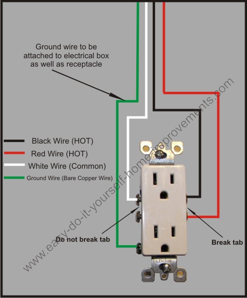
diagram wiring outlet Wiring Diagram and Schematics

Electrical Outlet Split Circuit Wiring Nice Wiring Diagram
Split Recepticle Wiring Electrical 101
15 Cleaver Wiring Diagram Of A Gfci Receptacle Solutions

Wiring A Gfci Outlet Diagram schematic and wiring diagram

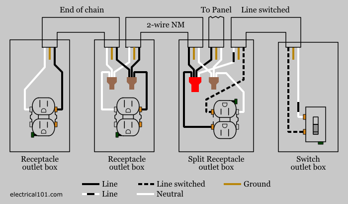
Split Recepticle Wiring Electrical 101
Gfci Split Receptacle Wiring Diagram Perfect Gfci Split


Wiring A Gfci Outlet With 2 Wires

Gfci Receptacle Wiring Diagram Free Wiring Diagram

how to replace a gfci outlet with 4 wires Wiring Diagram
Multiple Gfci Outlet Wiring Diagram / Wiring Diagram
Gfci Split Receptacle Wiring Diagram Wiring Diagram
Multiple Gfci Outlet Wiring Diagram / Wiring Diagram

Wiring Diagram For Light Switch And Receptacle / Wiring
