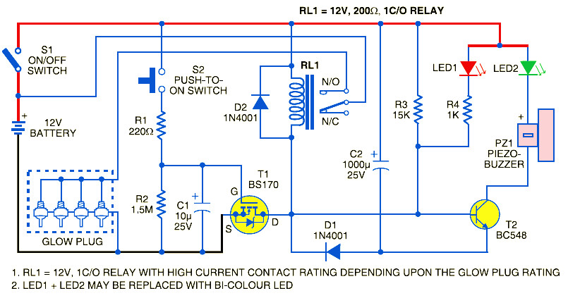
Mn 9645] glow plug timer circuit diagram glow plug timer. Posted by stephenbi on dec 03, 87 and/or loss of voltage to glow plug controller:
7.3 Powerstroke Glow Plug Relay Wiring Diagram Wiring
Turn key switch to ignition on.

Glow plug timer relay wiring diagram. Below is a amazing image for 6 2 glow plug controller diagram wiring diagrams. I need to change/repair the glow plug cable as it got damaged. Original harness is still installed, so timer relay is not present.
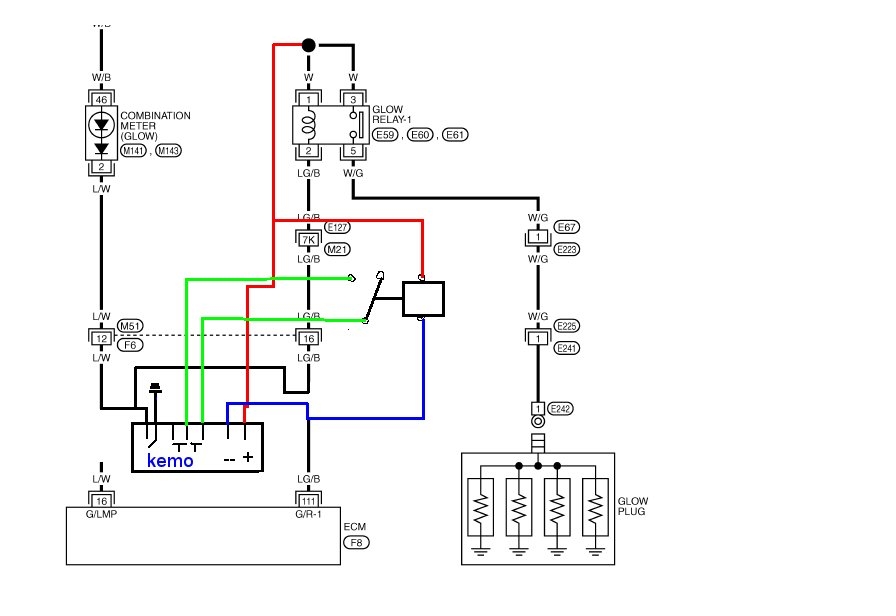
Please look at this picture: White wire to glow plug pre relay. It shows how a electrical wires are interconnected and may also show where fixtures and components might be attached to the system.
12+ dual electric fan relay wiring diagram wiring g2sonline january 1 to march 31 2020 $69 95 $159 95 mercedes 300e owners manual by mmamakas issuu glow plug current rail seat ibiza st vwvortex 91 cabriolet engine partment […] The red box is around your glow plug timer. Remove the 'glow plug current sensor' and the 'current sensor plate'.
Vehicle is a 90 and was originally fitted with a 19j engine, however it is now converted to 300tdi. We have been hunting for this picture throughout web and it came from professional resource. Diesel manual glow plug conversion when i wired mine manually (i had an even earlier different system than the ) i ran my ground wire from the solenoid to my momentary switch and used.
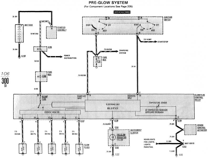
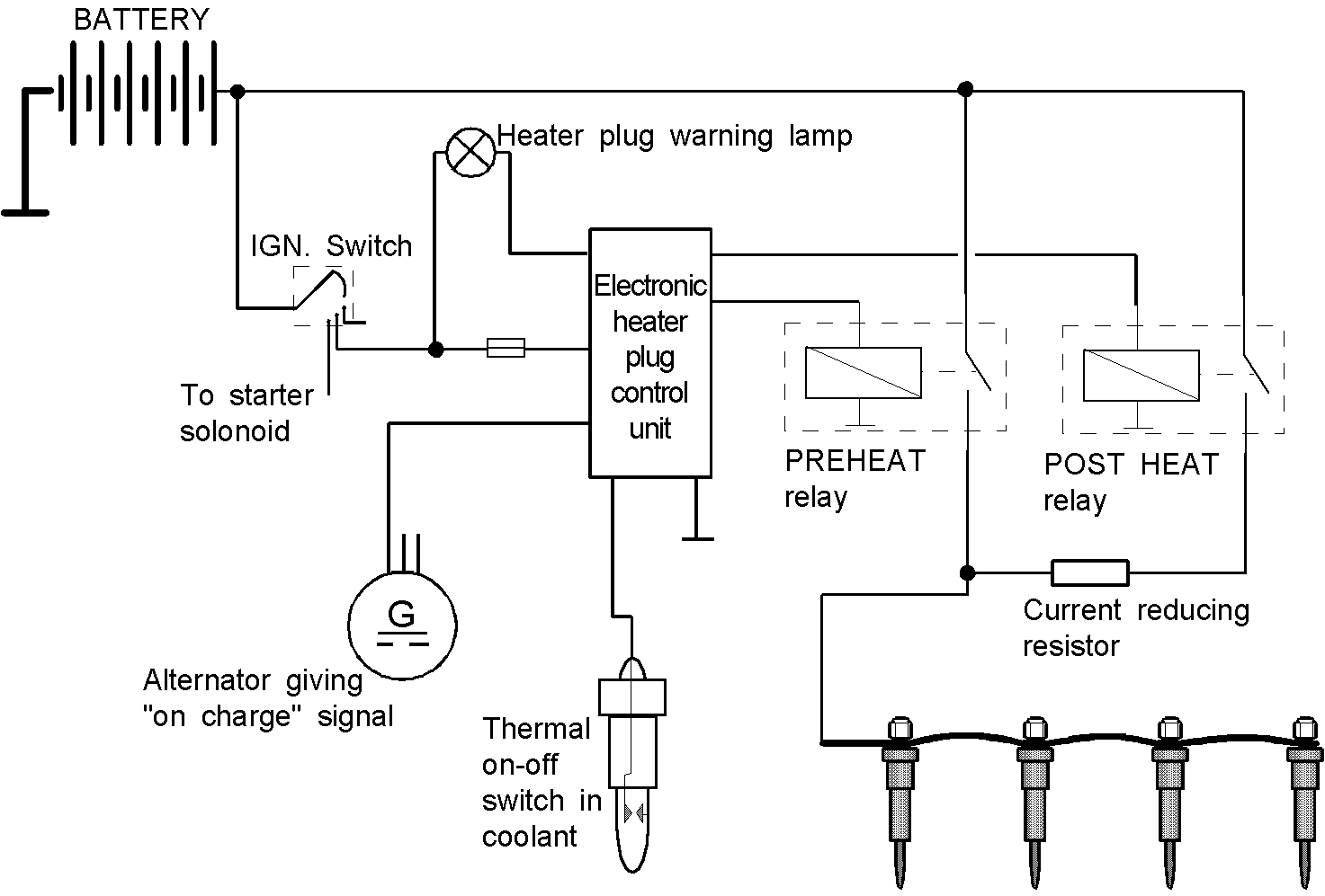
All of it depends on circuit that is being assembled. 7.3 powerstroke glow plug relay wiring diagram. The circuitry is designed to provide a couple of variable delays, after application of power via the glow and start positions on the ignition switch, based upon engine temperature,.
7 3 powerstroke glow plug wiring diagram wiring diagram is a simplified gratifying pictorial representation of an electrical circuit it shows the components of the circuit as simplified shapes and the faculty and signal contacts amongst the devices. Blue wire to ignition switch start position. Disconnect the cable from the 'outlet' side of the primary glow relay and run a new cable from here (at least the same diameter) to the first glow plug/bus bar.
Can anyone tell me the correct wire size i. You can buy the timer from your nh dealer for around $70, but a couple of people have said that they took the. At times, the wires will cross.
Mine doesn't have a timer, but this is how i wired up the relay when i changed to 12v parallel glow plugs on my siii. Orange wire to glow indicator light and switched to negative in glow timer. Occasionally, the glow plug relay will energize, or just remain 'on', as seen by the indicator lamp.
The objective is the same. If there is fire going into the timer from the power relay, pull off one of the glowplug wires and ground 1 end of a testlight and put the other end on the glowplug wire. This causes the glow plugs to come (or remain) 'on' during starting.
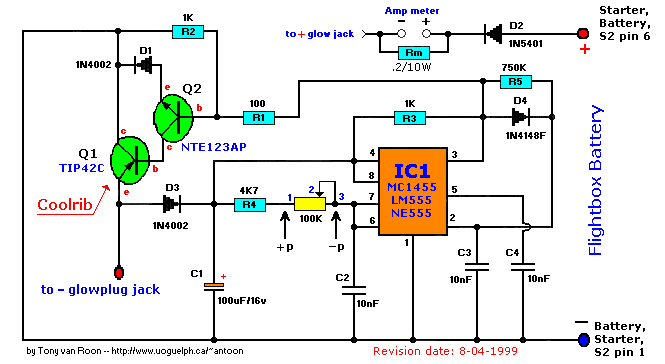
Glow plugs are powered up and. Solid state timer relay electrical academia time delay circuit with 555 8 pin wiring diagram and electronics technology degree using ic digital 12v 24v 220v ato com 326 327 series relays on struthers dunn dc 110 240v ac ah3 n 3a super inductive proximity sensor photoelectric capacity pcb asymmetric cycler best. Bosch glow plug relay wiring diagram december 9, 2021 by admin 1 view.
So, either the q2/q3 latch circuit failed, or timer q1. Red wire to key switch ignition on position. The timer itself will kill the power after a predetermined time based on temperature.
Homepage / wiring diagram / bosch glow plug relay wiring diagram. Step by step directions in wiring series type glow plugs, specifically in a bd 154 ih diesel engine. According to earlier, the lines in a kubota glow plug wiring diagram signifies wires.
The colder the engine, the longer the glowplugs stay lit. About press copyright contact us creators advertise developers terms privacy policy safety how youtube works test new features press copyright contact us creators. This diagram is from the hst model tractor, but the relays for the glowplugs are in the same place on your tractor.
12v glow plug converter circuit diagram. However, it doesn’t imply connection between the wires. The first this to do is attach the bare wire to the back of the electrical box wrap around one of the screws but leave enough of a tail to attach the the.
Item #10 is the glow plug relay, but most often it is the timer that fails. The wiring from the glow plug relay to the glow plugs should be 12 or 14 wire. The wiring diagram to the right shows the new wiring in.
To control a load (a lamp or a pump), we should connect the wire to normally open contact. Hy 2699] glow plug relay wiring schematic. Describe and identify the diagram component u.
Injunction of 2 wires is generally indicated by black dot in the intersection of two lines. Quick glow plug relay check about press copyright contact us creators advertise developers terms privacy policy & safety how youtube works test new features © 2022 google llc A wiring diagram is a simple visual representation from the physical connections and physical layout of the electrical system or circuit.
Insider Glow Plug Timer Circuit
Pajero Glow Plug Wiring Diagram

7.3 Powerstroke Glow Plug Relay Wiring Diagram Wiring

2001 Ford F 250 Powerstroke Glow Plug Wiring Diagram

Glow Plug Timer Relay Wiring Diagram SCRAPBOOKMAMAW
Glow Plug Timer Relay Wiring Diagram SCRAPBOOKMAMAW
7.3 Powerstroke Glow Plug Relay Wiring Diagram Cadician
Wiring Diagram For 7 Pin Plug
Help needed understanding the different HZJ75 Glow Plug
Glow Plug Timer Circuit Circuit Diagram Images
73 Powerstroke Glow Plug Relay Wiring Diagram General
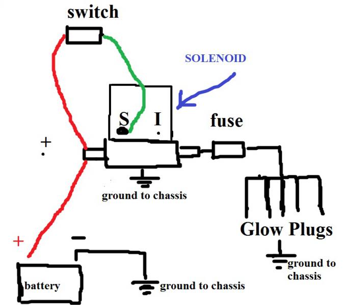
Table of Contents


Glow Plug Timer Wiring Diagram Collection Wiring
Glow Plug Timer Relay Wiring Diagram SCRAPBOOKMAMAW

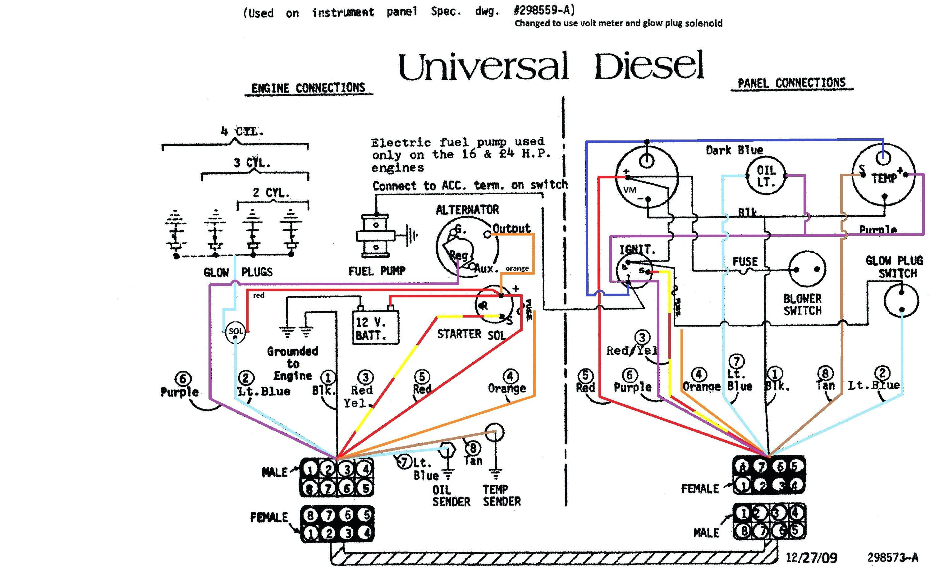
WKP Get How to wire a sailboat
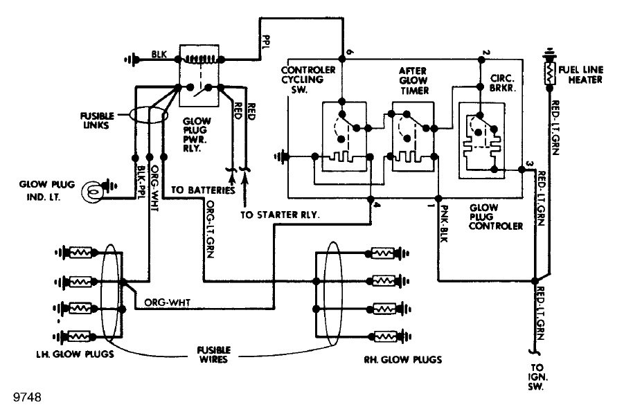
Glow plug controller troubleshooting 6.9idi Ford Truck

Glow Plug Timer Relay Wiring Diagram SCRAPBOOKMAMAW
Glow Plug Timer Circuit Circuit Diagram Images


I have a 96 F350 diesel. The glow plug circuit stays hot