
Heat is generated in the conductive. Heat tracing, systems comprise heating cables and ancillary items which necessarily interface with other system components such as thermal insulation and the electrical supply items which will power the system.
Heat Trace Cable, Heat Tracing, Heating Cable, Pipe

Wiring methods must conform to class 1, division ii or class 1, zone ii requirements.

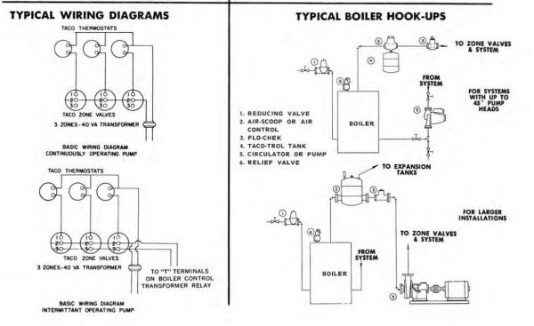
Heat trace wiring diagram. Check out the diagram below to see what a completed heat trace system entails. In the diagrams below the dotted lines indicate optional wires that may not be applicable to your specific hvac system. Isometric system diagrams (if provided).
Heat pump thermostat wiring diagram classy shape hvac why does wires. Heat trace thermostat wiring diagram wiring diagram and schematics wiring diagram and schematics this place is a growing library of the schematics, wiring diagrams and technical photos If no number appears in the cell, straight trace the pipe.
To aid in troubleshooting connect heaters as shown in figure 1. Do not use this kit with aluminum feed wires. The first step in designing a heat trace system is to determine the heat loss from each pipe or tank to be traced.
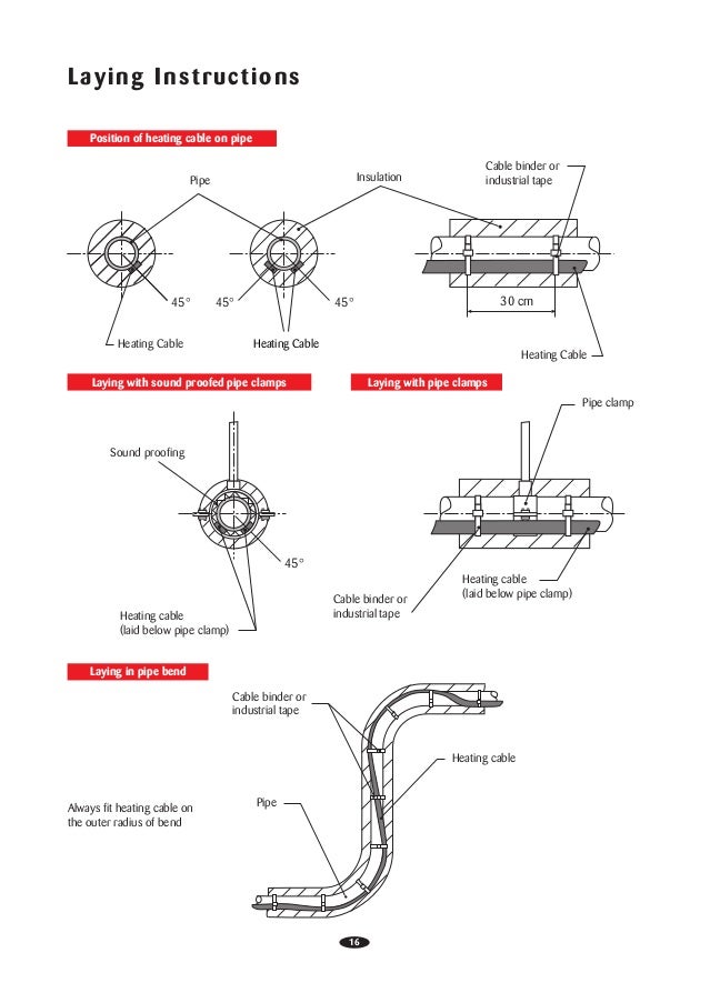
The collection that consisting of chosen picture and the best amongst others. Wrap bands of tape around the trace heater and pipe at intervals of 12” (30 cm) or less, keeping the trace heater in close contact with the pipe. An initial take a look at a circuit representation might be confusing, but if you could check out a subway map, you can review schematics.
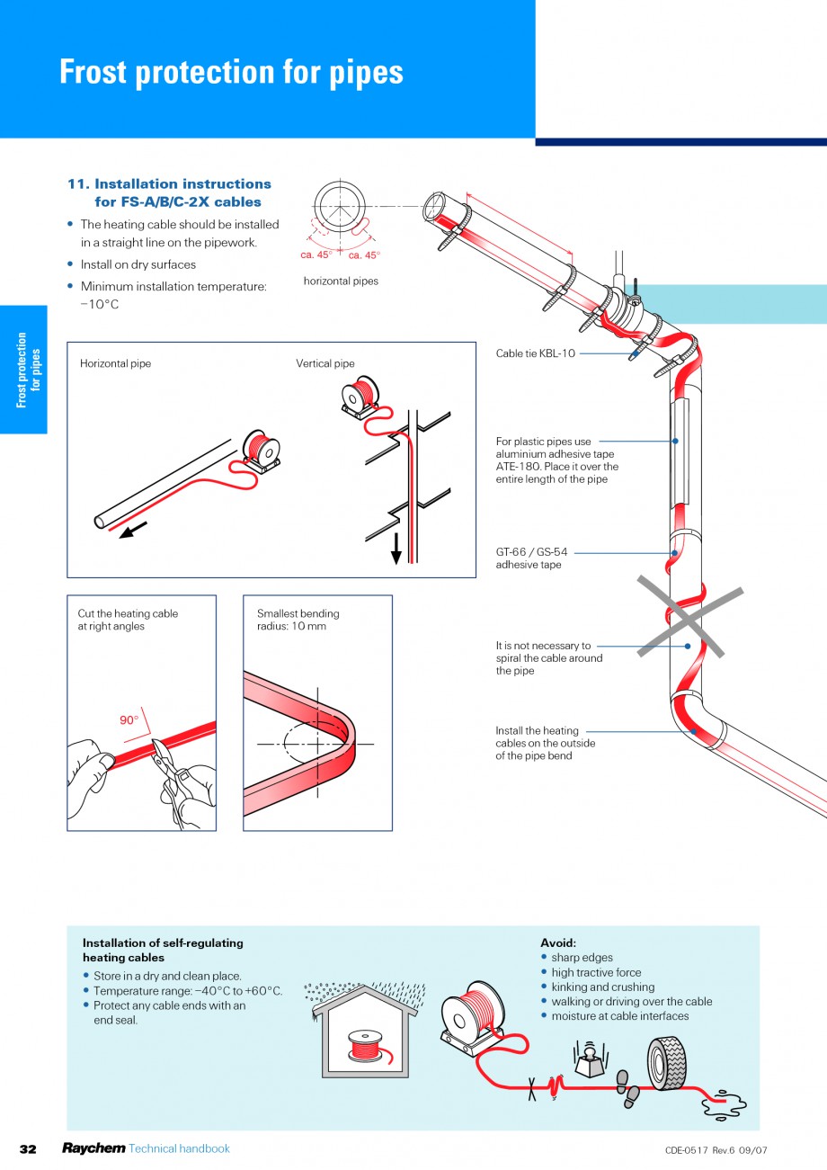
On raychem heat trace wiring diagram. • lay out the trace heater on the pipe, at the 4 or 8 o’clock position (illustration b), securing it tightly against the pipe with attachment tape. Electrical trace heating, or as it is often called heat tracing, refers to the process of maintaining or raising the temperature of instrument impulse lines, pipes, and even vessels through specially designed cables.
The function is the exact same: The bus conductors provide uniform voltage across the heating matrix by providing current down the entire length of the cable. Power should be brought to heater control panel from separate disconnect.
Their fluoropolymer jacket is moisture proof and its slippery texture lends itself to conduit pulling. Collect the following data for each pipe (for tank applications go to page 6). In simple terms, the application of a.
Heat trace cable wiring diagram have a graphic associated with the other. Heat loss calculations and system design. Electrical wiring diagrams and schematics are provided in appendixb andc of this manual.ensure that all wiring and connections are in accordancewith applicablewiring
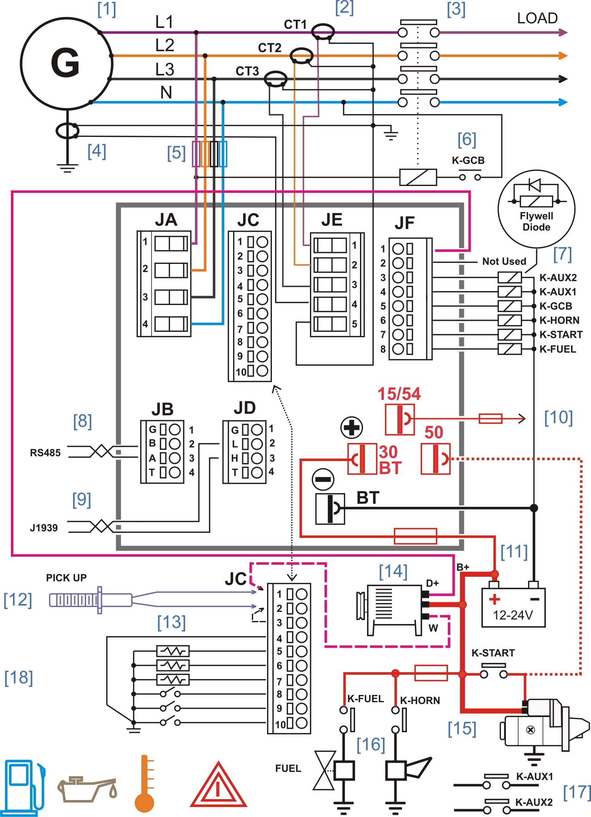
Wiring diagram chromalox heat tracing installation manual en us everything you need to know about trace powerblanket intech 21 inc overview products nelson clt28 cable modular connection selection guide manualzz 10 ways use electric keep fluids flowing in winter 2009 09 01 process heating 8 w ft 120v self reg tpe overjacket elettrico sistema di. The green (ground) leads must be connected to the grounding bar as per wiring diagram. Wiring diagrams comprise a couple of things:
Raychem heat trace wiring diagram. • heater control panel wiring diagrams and external heater cable circuit wiring diagrams are provided with the system. The intellitracetm family of heat tracing products continues to expand with its latest single or two circuit controllers the itc1 & itc2.
Heater wiring connect heatingcable wiring toterminals3 and 4.see figure 2.2. If the heating cable has a braid, it should be terminatedtothe ground studusing a ring terminal suitable for #10 stud. Provided heat trace wiring diagram.
Heat trace cable wiring diagram in addition, it will include a picture of a sort that might be seen in the gallery of heat trace cable wiring diagram. Symbols that represent the components inside circuit, and lines that represent the connections together. Tracerlynx compresses project design schedules by combining every element needed to design a full heat management system, including client information, design data and deliverables where the entire project can be seamlessly managed across.
A wiring diagram is a kind of schematic which uses abstract pictorial symbols to show each of the interconnections of components in a system. Heating cables are factory mutual approved for use in hazardous areas. • power must stay on to the heater control panel for system to work properly.
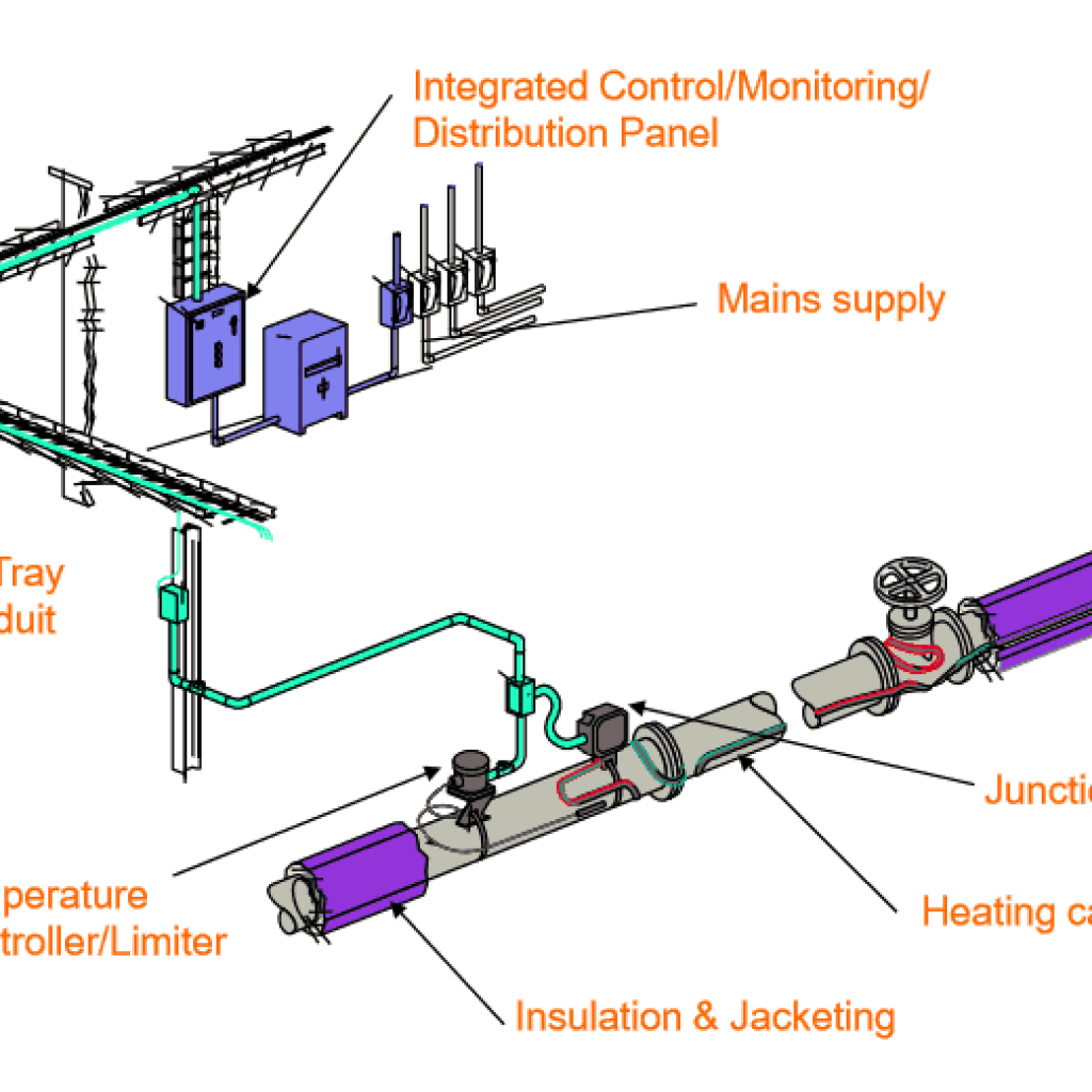
Voltage range of the heat trace cable. Obtaining from factor a to direct b. A heat trace system includes:
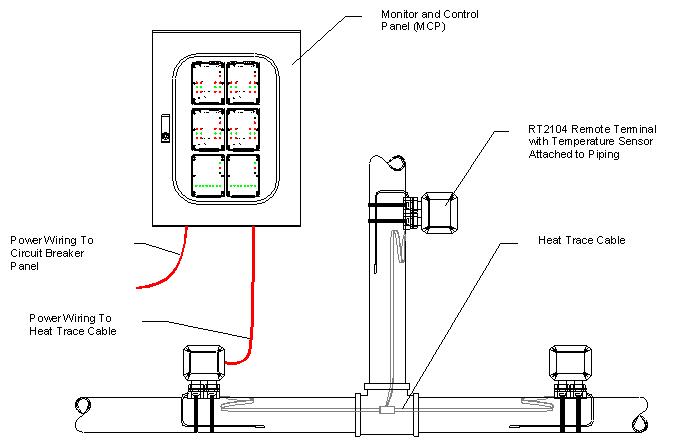
Heat tracing cables (self regulating heating cables, constant watt cables, or power limiting cables) applied to piping and tanks, often secured with fiberglass or aluminum. A control panel or thermostat. Each heat tracing application imposes unique demands on the designer to achieve the desired performance in a safe manner.
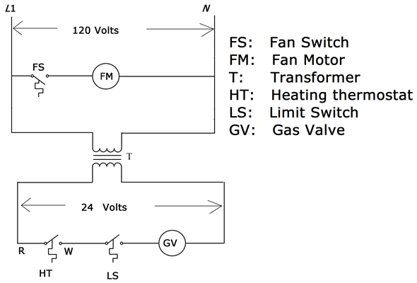
Heat trace thermostat wiring diagram. Literally, a circuit is the path that enables electricity to circulation. Consideration shall be given to the maintenance of the system and process equipment to energy efficiency and to.
Black heater leads should be connected to the odd numbered tabs and white leads to the even numbered tabs. Fully insulated terminals for 16awg wire and ¼” wide x 1/32” thick tab.
25 Heat Trace Wiring Diagram Wiring Database 2020
Raychem Heat Trace Wiring Diagram

Heat Tape Heat Tape Wiring Diagram
Raychem Heat Trace Wiring Diagram


Heat Trace Wiring Diagram Collection
Raychem Heat Trace Wiring Diagram

Electrical Heat Tracing System, Heat Trace Cable Supermec

Heat Trace Wiring Diagram Gallery Wiring Collection

S Plan Central Heating System Lively Heat Trace Wiring
Raychem Heat Trace Wiring Diagram
Raychem Heat Trace Wiring Diagram
Heat Trace Wiring Diagram

Heat Trace Wiring Diagram
Heat Trace Wiring Diagram Free Wiring Diagram

Heat Trace Wiring Diagram Free Wiring Diagram


Heat Trace Wiring Diagram Collection
Heat Trace Wiring Diagram Hanenhuusholli

Heat Trace Wiring Diagram Gallery Wiring Collection

Heat Trace Wiring Diagram Collection