
Pilot gas is ignited and burns during each run cycle (intermittent pilot). In turn the pilot flame lights the main burner gas.
Honeywell S8610u Wiring Diagram General Wiring Diagram
Taking into consideration aggravating to remove, replace or repair the wiring in an automobile, having an accurate and detailed intermittent pilot.
Intermittent pilot ignition wiring diagram. All the major hardware stores and hvac dealers carry standing pilot appliances. I ordered a replacement one. To find out just about all pictures within honeywell s8610u wiring diagram photographs gallery make sure you comply with this specific hyperlink.
View and download honeywell su installation instructions manual online. That graphic (honeywell s8610u3009 universal intermittent pilot ignition module for honeywell s8610u wiring diagram) over can be branded along with: Intermittent pilot modules s8600, s8610, s8660, s8670 application these ignition modules provide ignition sequence, flame monitoring and safety shutoff for intermittent pilot central furnaces and heating appliances.
Main burner and pilot gas are extinguished during the off cycle. Connect to gas control terminals as shown in wiring diagrams, using. S8600 and s8660 models provide up to 1.0 a pilot and 1.0 a main valve current rating.
S8610 and s8670 provide up to 1.0 a pilot and 2.0 a main valve current rating. Wiring diagram for g67b( ) Check porcelain is not cracked on flame sensor.
However, with everything else now days, the newer one does not match the older one. Pilot gas provides labels to help assure proper marking of the wires. Do not connect any wires to unused terminals.
How to wire and install an ignition control hvachoneywell s8610u universal intermittent pilot control the s8610u universal replacement ignition module is des. Clean flame sensor rod and any corrosion from pilot assembly 4. • vr8204 intermittent pilot cgc s8610u intermittent pilot ignition module burner with pilot burner and pilot gas hose attached burner bracket propane bottle connector, regulator, hose & quick connect procedure 1.
Q refer to the wiring diagram and. Direct vent, zero clearance gas fireplace heater millivolt standing pilot, direct ignition, intermittent pilot,remote rf (80 pages). The g670 is used to automatically light a pilot burner and energize the main burner gas valve in response to a call for heat from the system thermostat.
The su replaces existing flame rectification type. The su universal replacement ignition module is. The ignition control module’s operation is divided into two phases:
Do not connect the thermostat wires to the control board until wiring is verified. Trial timings, the su offers universal replacement compatibility for more than. Submitted through admin on january, 3 2016.
Vr8304 type of gas natural or lp flame sense single rod or two rods ignition source internal high voltage spark generator ignition trials to lockout continuous retry lockout timing 15 or 90 seconds ignition trial time(sec) 15 or 90 seconds maximum valve load@ 24 vac(amps) 1a pilot. Verify the sequence of operation. When the call for heat
1) trial for pilot ignition and 2) main burner operation trial for pilot ignition 2a main@ 24vac typical ignition hardware q345. If cracked replace flame sensor 5.
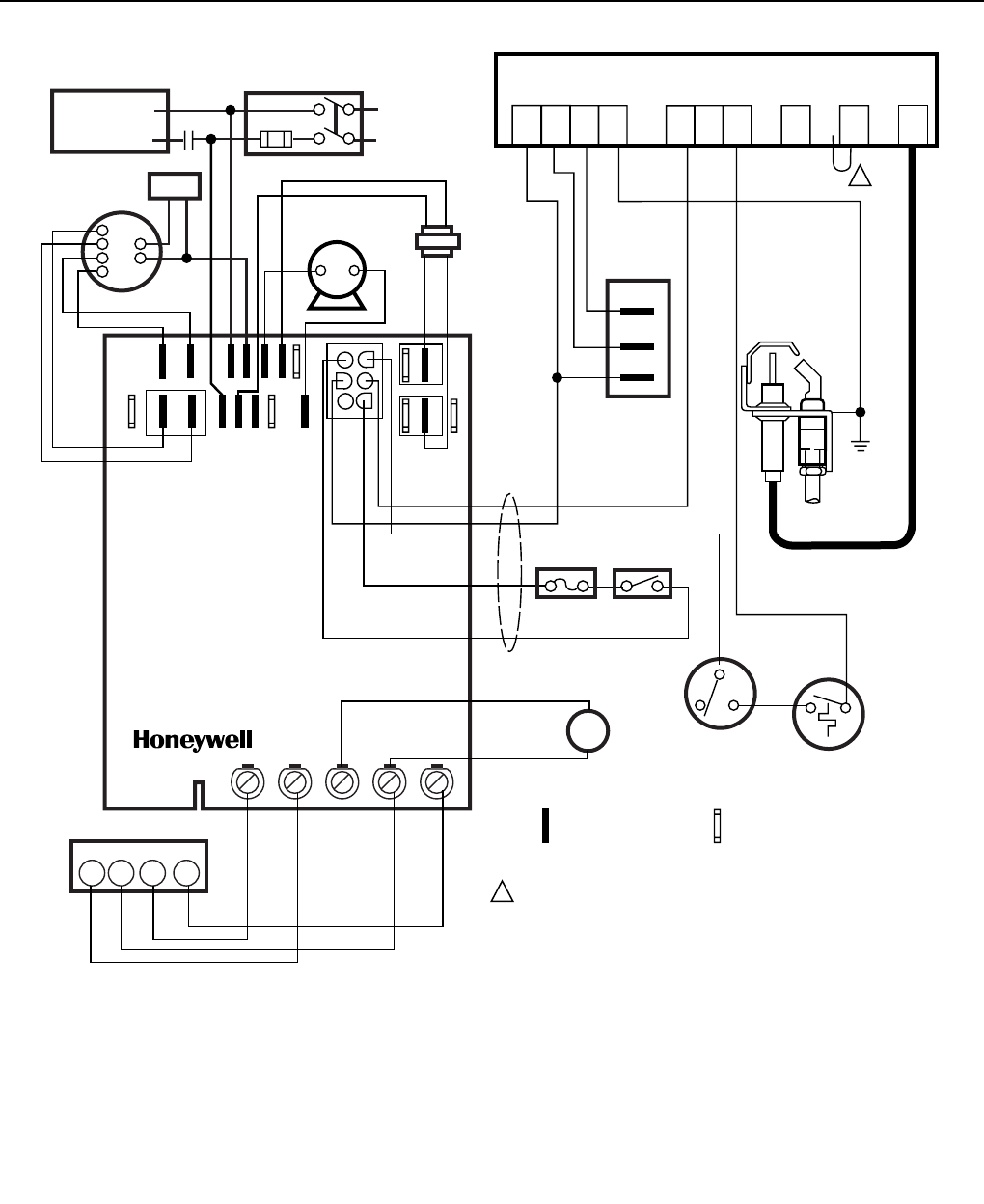
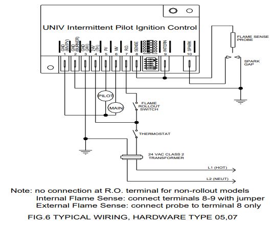
(some of the checks can also be applied to direct spark ignition systems.) these are things that techs should look at as preliminary checks before proceeding with troubleshooting charts and wiring diagrams. 8 g67 intermittent pilot ignition controls technical bulletin y75 flame sensor thermostat power supply 24 vac 1 2 4 3 high voltage cable high limits in this line only jumper pilot burner ground ground terminals mv pv 5 power is wired directly to r (common) on the thermostat. When enough heat is generated in the thermocouple, the gas valve allows gas to the main burner and is ignited by the pilot until the call for heat is satisfied.
See flame detection specifications for correct wiring. All applications must use a redundant main gas valve. These ignition modules provide ignition sequence, flame monitoring and safety shutoff for intermittent pilot central furnaces and heating appliances.
Verify flame sensor wire is properly connected to module and the system is grounded 3. Clip jumper jr2 if using 3 second flame response time. The intermittent pilot ignition control is short cycling.
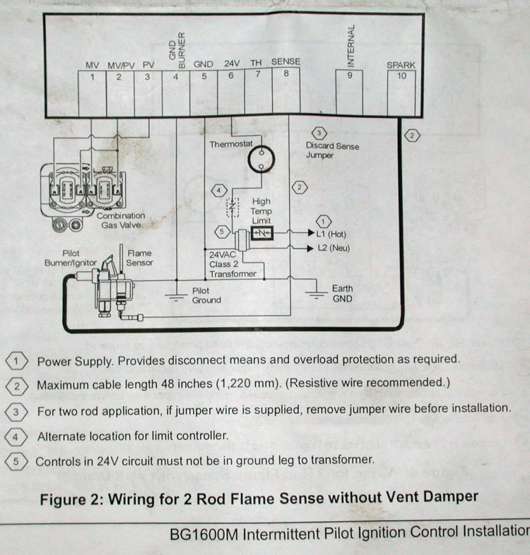
Provide disconnect means and overload protection as required. The burden really is that every car is different. The main gas valve will not open until the pilot flame has been proven by the sensing circuit.
View and download honeywell su installation instructions manual online. The procedures outlined in this article are for checking out all systems that use an intermittent pilot. If sparking continues, replace dfc board yes no
Check the wiring diagram furnished by the. Terminals 1 and 2 on the g67 are tied together internally. The intellifire system (intermittent pilot ignition) is an electronic system, which uses an electrode to ignite the pilot gas.
The term ”intermittent” is used because the pilot burner flame is only present when the main burner is operating. Wire per wiring diagrams on reverse side. Pilot gas provides labels to help assure proper marking of the wires.
Attached.my assumption (confirmed via wiring diagram) is. • to connect the vent damper, the wire from pin 1 should be connected to 24vac hot from the supply transformer. S8610 and s8670 provide up to 1.0 a pilot and 2.0
Q locate the components needed for this lab and mount them on the trainer. Verify flame sensor is in the pilot flame, adjust flame as needed 2. Bg1600m intermittent pilot ignition control this model is configured to replace the s8670d 15 sec trial until lockout prepurge:
This should be the only wire attached to the ths terminal.

Honeywell S8610u In Place Of Honeywell S8600m Wiring Diagram
Damper Wiring Diagram For S8610u
Honeywell S8610U Wiring Diagram Honeywell S8610u
Honeywell S8610U Wiring Diagram / Honeywell S861ou 1009
Universal Furnace Ignition Kit Wiring Diagram Complete

Honeywell S8610U Wiring Diagram Honeywell S8610u

S8610u Wiring Diagram

Honeywell S8610U Wiring Diagram Honeywell S8610u
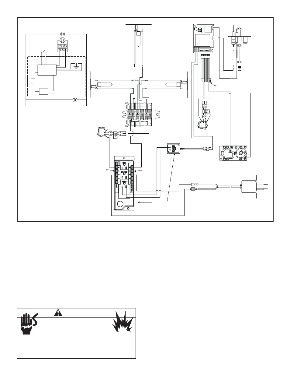
Step 8. wiring the fireplace, Warning, For intermittent

Honeywell S8610U Wiring Diagram / Honeywell S861ou 1009

How to connect a Nest thermostat to a gas fireplace
33 Honeywell S8610u Wiring Diagram Wiring Diagram Database


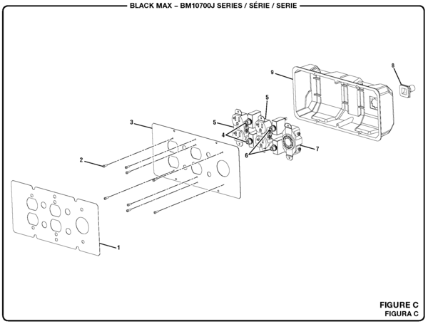
Heat & Glo LifeStyle 6000TRIIPI, 6000TRISP Figure 36

Damper Wiring Diagram For S8610u

Honeywell S8610U Wiring Diagram Honeywell S8610u
Honeywell Ignition Module Wiring Diagram Wiring Diagram
Honeywell Ignition Module Wiring Diagram Wiring Diagram


Honeywell S8610U Wiring Diagram / Honeywell S861ou 1009

Honeywell S8610U Wiring Diagram / Honeywell S861ou 1009