Ms1 + ms2 programmable output wiring; A typical wiring diagram of an earth leakage relay is shown below.
.png.f101987d0306ca21f1ddc81bcfbf9c1b.png)
magasqirt wiring diagram MegaSquirt HybridZ
Microsquirt has a flexible triggering input it can be triggered from a distributor or a multi tooth crankwheel.
Ms2 wiring diagram. So i am not sure on which connection to make on the board since : See the ignition hardware manual for details on controlling different ignition systems and the diy options for multiple spark outputs. Here are the main application specific wiring details to keep in mind.
Below is a wiring diagram for a do it yourself 2 speed switch. A wiring diagram is a streamlined standard pictorial depiction of an electric circuit. The qrs complex, which represents the depolarization of the ventricles;
Ms1 + ms2 knock input; Marshall ms2 diagram html wiring diagram arrives with several easy to stick to marshall ms2 diagram html wiring diagram directions. Definitely needed when troubleshooting a missing tone or frequency.
Lv8729 uses 0.10ohm current sense resistor, so the current limits can be calculated as follows: 0 to 1250 ω max; • ms2 on a v3.0 mainboard as shown above running firmware ms2/extra 3.3.x does not apply to other megasquirt products or other firmware versions.
Additionally the low speed coil is typically supplied by a red wire while the high speed coil is fed by a black wire. Operational power is applied to the terminal a 1 and a 2 of the elr and the cbct is connected to the terminals t 1 and t 2. I do not see any wiring diagrams for ms2 that show distributor, coil and igniter.
Mostly, you’ll use the wiring diagrams in the ms2/extra microsquirt hardware manual. This circuit is the same as the master on circuit the only change is an additional master switch (ms2) which is added to the phase line that was previously connected directly to the terminals of switches s1 to s4. If you are using the relay board, use these diagrams.
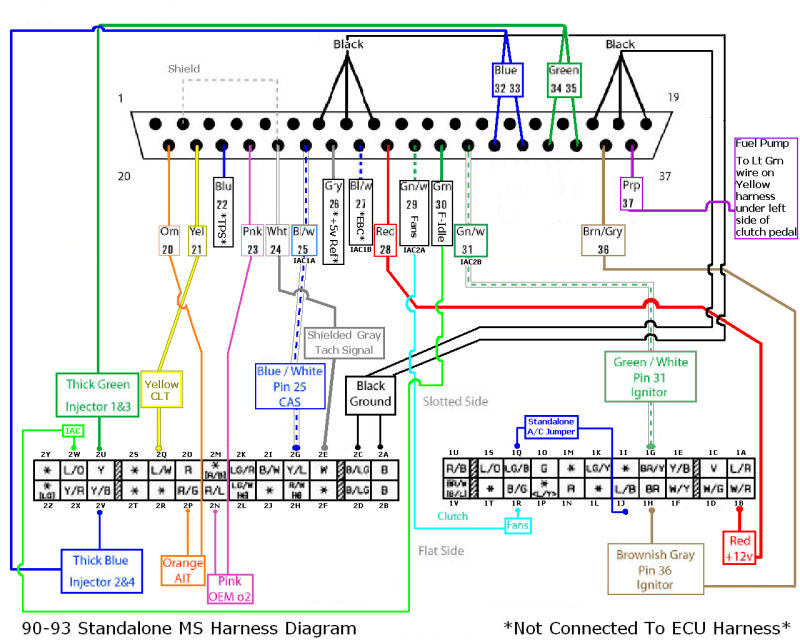
Ms1 + ms2 launch control wiring; Click the wiring diagram image for a larger view note: 4l80 wiring diagram the 4l80e transmission has two speed sensors, 4l60e only used one.
And the t wave, which represents the. Below is an example wiring diagram depicting the installation of a quadspark with the mspnp2: You will now have two extra wires, these will be used for the 4l80e's input speed.
The normally closed terminals of the fault signalling contacts are connected to the undervoltage release coil of the circuit breaker. Ms2 + ms3 stepper motor idle valve options; Averaging 0 to 240 s, 2.5 hz sample rate, 1.5 to 228 s for 95% step change.
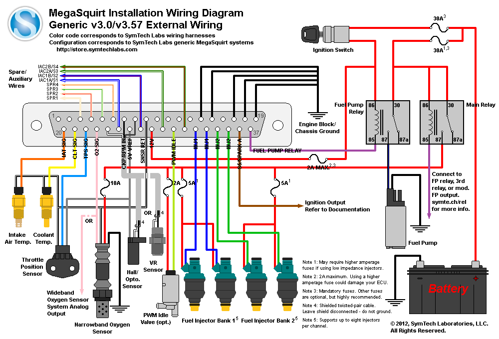
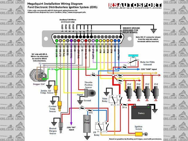
This is a general external wiring layout. This is connected to pin 14 of the 40 pin socket (irq), and pin # 1 of the mc9s12c32 processor. Ms1 + ms2 pwm idle valve options;
Ms1 + ms2 shift led/warning led; This wiring arrangement can turn on or off lamps irrespective of their individual switch positions. Hardware manual covering specific wiring and configuration of your megaquirt ms2/v30 ecu.
The p wave, which represents the depolarization of the atria; This version of the documentation applies to: External wiring schematic (this wiring diagram is for those creating their own harness for a v2.2 main board.
This is what you'll refer to for the locations of all tweakable/adjustable features on the board. Ms1 only water injection wiring; Mazda miata wiring diagrams 1990 to engine diagram mx 5 forum every factory work manual problem rpm signal ms2 turbo 96 standalone 1 6 1996 m edition nb comboswitch for ls 8 maf help
If you are using the wiring harness then you are wiring everything directly back to. In most cases you won't need these at all. Wiring diagram¶ motor current setting¶ current limits can be adjusted by measuring the vref and the adjustable resistance (pls check wiring diagram).
Ms1 + ms2 switchable maps wiring; Click the image for a large wiring diagram. You can also wire this to communicate with an ms2, 4l80e wiring harness diagram.
4l80e nnbs t42 wiring (thank you chris ortiz for the writeup). These functions correlate to the pins listed in the m50 pin no. There are three main components to an ecg:
The wiring harness and relay cable are ‘mutually exclusive’, meaning they are not designed to be used together. [current limit = vref x 2] Integration with megasquirt and microsquirt ecus using can is available to reduce wiring by sharing sensors.
Slow speed as shown in the wiring diagram above and not the fast speed. If you are using a v3 main board, use this wiring diagram.) external wiring with a v3.0 main board Ms1 + ms2 boost control wiring;

Megasquirt 2 Miata Turbo Forum Boost cars, acquire cats.
How To Megasquirt Your 2nd Gen RX7 Wire The ECU Panel
2jz Megasquirt help Toyota L6 Forum HybridZ
20 Beautiful Megasquirt Wiring Diagram
Megasquirt 2 External wiring layouts
How To Megasquirt Your 2nd Gen RX7 Wire The ECU Panel
Megasquirt Support Forum (MSEXTRA) • i have ms2 v.3 i want
How To Megasquirt Your 2nd Gen RX7 Wire The Megasquirt
Sequential Injection Code for MS2
MegaSquirt 2 Embarrassingly Noob Questions R3VLimited Forums

Help wiring the MS2 Miata Turbo Forum Boost cars
Megasquirt 2 Wiring Diagram Wiring Diagram

Megasquirt 3 Wiring Diagram Diagram, Jet engine, Wire
How to megasquirt a Vauxhall engine, with MS2 v3


