Basics 14 aov schematic (with block included) basics 15 wiring (or connection. The g wire is green and connects to the fan.
Master Heater B99 Wiring Schematic Wiring Diagram
A propane (lpg) fired heater must not be installed in a garage in massachusetts, by order of the massachusetts state fire marshall.

Torpedo heater wiring diagram. F271802 which includes a quick disconnect fitting and a 3/8”. Caution do not set thermostat below 60°f (16°c) in heating mode. If you know a little bit about home heating and cooling systems, you probably realize that they are pretty complicated little systems!
Connect to the accessory power terminal block (sl585u/ul or sl595u/ul only) connect to an external 12v to 24v dc or ac power supply (not provided) with an adequate current to power all sensors' heater. For heating and cooling systems, it will have a red rc and a red rh wire. Keep all combustible materials away from this heater.
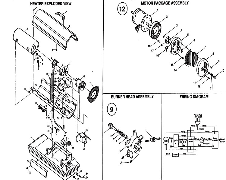
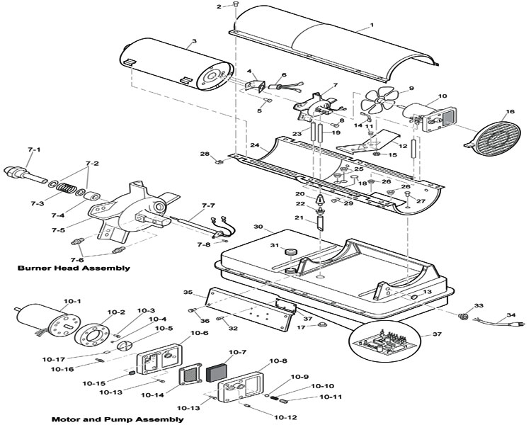
Once you select the type number the diagram, part list, and manual will become available. Always unplug the heater when not in use. 12 wiring diagram 16 13 specifications 17 14 exploded parts drawing 18 15 parts list 19 1.
And wire routing in the u.s.a., wiring must conform with current local codes and the current national electric code (nec). (305 cm) always locate heater on a stable and level surface. If you are unable to locate the model, manual, or parts list, please contact us for further assistance.
Check line cord with ohmeter. 4 kerosene forced air heater user’s manual unpacking remove the heater and all of the packaging materials from the shipping carton. Check the diagram on the following page to be sure that you have all of the parts required to assemble your.
If not, check line in pins 1&4. Basics 9 4.16 kv pump schematic : Basics 10 480 v pump schematic :
Click herethis part will ship within 7 to 14 business days after your order is placed. Basics 13 valve limit switch legend : Dayton heater 3 operating instructions & parts manual (16 pages, 0.92 mb) dayton heater 3 operating instructions manual (12 pages, 0.77 mb) 3.
In canada, wiring must conform with current local codes and the current canadian electrical code (cec). F273704 buddy series hose, fuel filter not required. F273701, f273702 or f272702 and fuel filter f273699.
In the electric water heater and thermostat wiring series, we will be showing the continuous i.e. Save the box and packaging materials for future storage. Setting thermostat below 60°f (16°c) reduces the number of heating cycles.
When replacing the heating element, be certain that you have an element that has the same rating for voltage and wattage. In canada, all electrical wiring and grounding for the unit must be installed according to the current regulations of the canadian electrical code part i (csa standard c22.1) and/or local codes. 2017, pinnacle climate technologies, inc.
Heater flame sensor kit for all kerosene forced air heaters. Features hot air outlet lower shell fuel gauge. Connect to the accessory power on terminal on the control board.
When the fan runs, but the heater produces no heat, look for a defective heating element, or loose wiring. Introduction please read this user’s manual carefully. If your thermostat is dedicated to air conditioning only, it will have a red rc wire.
Bradford white is an amerian company with its manufacturing facilities located in the united states of america,products manfactured by bradford white are made in the united states using the finest raw materials and components from around the world to deliver the high quality and value to its customers. For more information, call the fire marshall’s office. Dayton heater 3ve53h operating instructions manual (18 pages, 4.29 mb) 2.
Precisely matched orifice plates meter the air and gas into the mixer. Schematic diagrams for hvac systems: Or more beyond the heater in all directions.
Heater is not suitable for use on wood floors or other combustible materials. Refer to the furnace or air handler installation instructions for additional wiring application diagrams and refer to unit Fuel filter must be replaced annually.
The y wire is yellow and connects to your air conditioning compressor. Request us to beat a competitor's price. The red wire(s) are the power source for your thermostat.
Inside those compact units are electrical connections, fans, compressors, condensers, switches, coolants—the list goes on and on. What you need to know. Heater big buddy 4 operating instructions and owner’s manual never leav e the heat er una ttended while burning!
Always install the heater so that it is not directly exposed to water spray, rain, dripping water, or wind. Check the wiring in the heater and solder any loose wires (making sure the heater in unplugged first). When used, the heater should rest on suitable insulating material at least 1 inch thick and extending 3 ft.
4.6 out of 5 stars 180. Never refill the heater’s fuel tank while the heater is operating or still hot. Basics 8 aov elementary & block diagram :
Check to make sure switch on top of control panel is in the on position verify primary and secondary voltage at the control board. When you use a portable heater, remember that you cannot smell or see carbon monoxide. Locate heater at a safe distance from combustible materials.
Never use fuels such as gasoline, benzine, paint thinners or other oil compounds in this heater. The heater wiring (green and white wires) may be powered in one of three ways: If your heater is equipped with a thermostat, once it
TORPEDO FIRE CONTROL EQUIPMENT (DESTROYER TYPE) Part 4


Vintage Electric Heater TORPEDO 350 eBay

Century Portable Heater Wiring Diagram Wiring Diagram
Reddy Heaters
Master Heater B99 Wiring Schematic biokonyha

Reddy Heaters
Wiring Diagram For Dayton Heater Complete Wiring Schemas


Master Heater B99 Wiring Schematic Wiring Diagram

Beacon Morris 75000 Btu Garage Heater Parts Dandk Organizer

GreatNeck 205Piece Household Tool Set with Hard Case

Master Heater B99 Wiring Schematic biokonyha

TORPEDO FIRE CONTROL EQUIPMENT (DESTROYER TYPE) Part 4
Master Heater B99 Wiring Schematic Wiring Diagram

Master Heater B99 Wiring Schematic biokonyha

Master Heater B99 Wiring Schematic Wiring Diagram
U.S. Navy Torpedo Mark 18 (Electric)


TORPEDO FIRE CONTROL EQUIPMENT (DESTROYER TYPE) Part 4
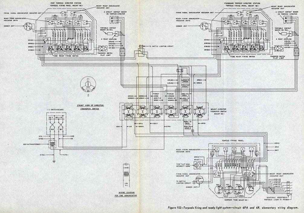
TORPEDO FIRE CONTROL EQUIPMENT (DESTROYER TYPE) Part 4
Master Heater B99 Wiring Schematic Wiring Diagram
