However, it doesn’t imply connection between the wires. I noticed the solenoid was hot, so i figured it had been energized for a while.
Battery Isolator Switch Wiring Diagram For Your Needs
March 22, 2010 at 5:08 pm / ip logged.

Battery isolator solenoid wiring diagram. Disconnect your main battery positive cable at this time and replace it with two new cables of suitable length. No matter how many batteries your adding each one of them needs to be isolated. Car audio wiring how to wire a battery isolator.
At times, the cables will cross. If the unit detects that either battery has exceeded 13.2 volts, then the isolator will be connected. A solenoid battery isolator does not.
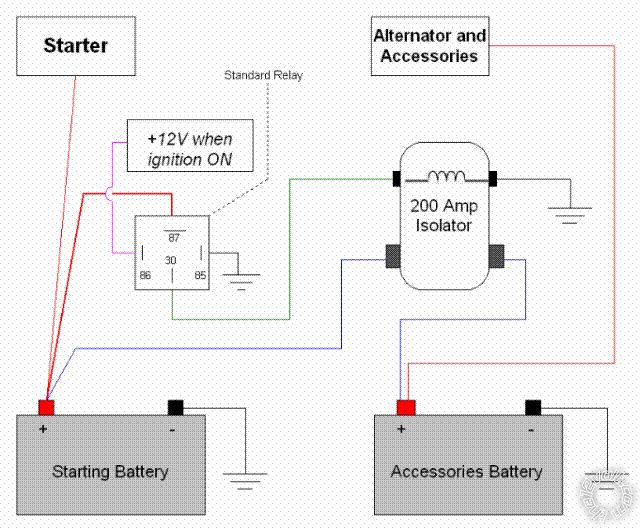
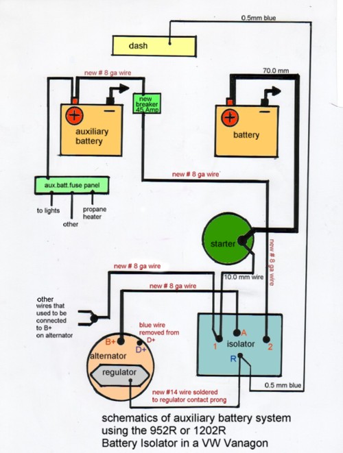
In addition, wiring diagram provides you with enough time body in which the assignments are to be completed. The original wire from the alternator to the main battery would be removed from the battery and installed on terminal 1. The solenoid isolator uses a continuous duty solenoid to connect the auxiliary battery during certain times (like starting and charging) then disconnects when not in use.
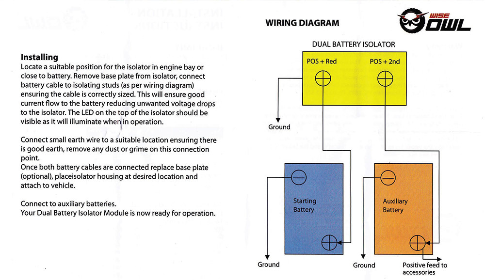
Remove earth from main battery and mount the isolator ( with the red and black wires the auxiliary battery. Carefully drill around the isolator attaching it to the frame with the sheet metal screws. I have posted a photo of a wiring diagram for the tr118665 battery isolation solenoid for you to review.
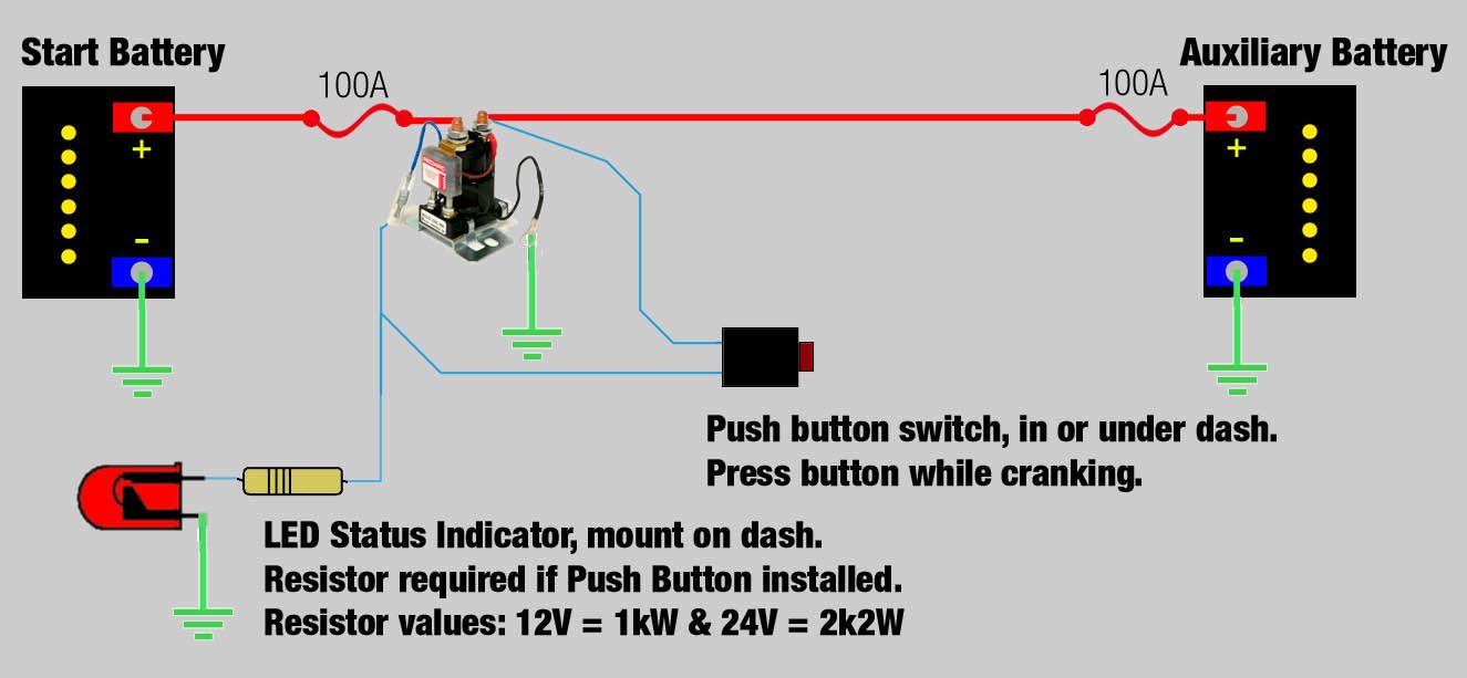
Cars trucks rvs and motorhomes run dual 12. Run another wire from the circuit breaker to the auxiliary battery, connecting one end to the bat terminal of the circuit breaker and the other to the positive + terminal of the auxiliary. Standard wiring diagrams dual sensing smart battery isolator fault indication dual sensing smart battery isolators monitor both the start battery and the auxiliary.
By allowing one battery to be run down completely dead, and firing up the vehicle, the relay will swith over to the dead battery and cause the alternator to run wide open untill the dead battery comes up. One is input into the isolator, that would be the wire that comes from the stator, and connected to the original battery. As stated earlier, the lines at a sure power battery isolator wiring diagram signifies wires.
You will be capable to learn precisely once the assignments needs to be accomplished, that makes it much easier to suit your needs. The smart start® sbi is designed specifi cally for use in multi battery applications as a solenoid priority system to protect the start battery from being excessively discharged by auxiliary loads, whilst still allowing the auxiliary battery to supply non essential loads. Both cables are secured to the same side of the isolator solenoid.
One (1) must run from the battery to the isolator solenoid and the other from the starter solenoid to isolator solenoid. You need to remove that wire from the battery and connect it to the center connection, of the isolator. Battery isolators and relays are a good way to toast your alternator.
I removed the cover from the bcc and measured the voltage on both sides of the isolator solenoid, voltages on the solenoid were the same as the batteries, chassis = 0 (zero) , coach = 13.2. Once you have hooked up the isolator you can do the actual wiring. Another wire connects the relay to the positive post of the sli battery, and another runs back to the rv.
Wiring diagram arrives with several easy to adhere to wiring diagram guidelines. Solenoid a determines whether the second battery is connected to the rest of the charging system or not. These guidelines will likely be easy to understand and implement.
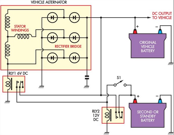
Below is a diagram that shows the process. Another thing you will discover a circuit diagram would be traces. The lhs in grey shows the additional fuses and battery when adding a second/aux battery, and the relay/isolator when battery isolation is used.
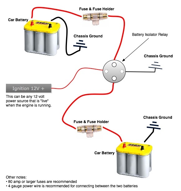
A solenoid isolator uses several electrical relays to control the flow of electrical current. The solenoid isolator is relatively inexpensive—it’ll set you back less than $20. For your battery isolator similar to # dw08771, you will have connection posts for each battery and for an alternator.
I've found a wiring diagram for the # dw08771 battery isolator. Terminal e would connect to an ignition circuit that's hot only when the. Run the wire to the circuit breaker and connect it to the aux terminal.
Depending on how the solenoid is wired, it can be switched to. The main battery will connect to position one and the alternator to the a post. You simply need to find a source of power from a circuit that’s only hot when the ignition system is “on,” and run it to the relay.
Schematron.org mount the isolator high up in the engine bay away for the isolator wiring diagram dbm4 battery protector (monitor) a dual battery kit does not necessarily protect you from overloading the vehicle's. Additional relays transmit the charging current from the alternator to the idle batteries. There are two things which are going to be found in any dual battery isolator wiring diagram.
The second battery will attach to the 2 via a circuit breaker that is rated appropriately for the battery. Again, hold it on tight so that you can secure it completely flush with the frame. By using a solenoid the amount of heavy wiring needed to power the load is reduced since the control circuit mounted on the panel typically utilizes a smaller wire gauge.
One of the relays receives the electrical current from the battery, while the other relay (known as the central relay) monitors the power levels of the idle batteries. On a diode isolator, there are only 3 large connections. A circuit is generally composed by various components.
The solenoid isolator uses a continuous duty solenoid to connect the auxiliary battery during certain times like starting and charging then disconnects when not in use. The diagram below shows two solenoids. This type of isolator uses large high current relays to control the flow of current.
It’s meant to aid all the common consumer in building a suitable method. Connecting multiple batteries can intimidate the do it your self installer, however the process is fairly simple when broken down. We need a whole new concept for it and one of these is this noco battery isolator wiring diagram.
Solenoid wiring diagram cole hersee battery isolator wiring 2000 arctic cat panther 550 s2000pacaaus battery solenoid details about projecta dbs085k dual battery system isolator kit 4x4 4wd 85 amp 12v 12 volt Output from the second battery positive post. Terminal 1 would connect to the positive battery terminal of the main battery.
The first component is symbol that indicate electrical element from the circuit. The smart start® sbi is a microprocessor controlled smart battery isolator. Injunction of 2 wires is usually indicated by black dot in the junction of 2 lines.
Solenoid b connects the second battery to the distribution block. I checked the voltage at the coil terminal and i seen 12.5 volts.

Cole Hersee Battery isolator Wiring Diagram Free Wiring

Dual Battery Solenoid Wiring Diagram For Your Needs
34 Continuous Duty Solenoid Wiring Diagram Wiring

Noco Battery Isolator Wiring Diagram

Cole Hersee Battery isolator Wiring Diagram Free Wiring
200 Amp Relay and Automotive Battery Isolator Oznium
OWL VOLTAGE SENSITIVE RELAY 12V VSR ISOLATOR 140A DUAL

Collection Of Automatic Charging Relay Wiring Diagram Download

Sure Power Battery isolator Wiring Diagram Download
battery isolator relay wiring diagram

Ik ben een autoliefhebber 4 Pole starter solenoid wiring

Redarc Smart Battery Isolator intermittent switch wiring
Battery Isolator
What’s the deal with wiring up a battery isolator? I have
Simple Battery Isolator Circuit Diagram

Cole Hersee Battery isolator Wiring Diagram Free Wiring
55 New Battery isolator Relay Wiring Diagram

Winch Battery Isolator Wiring Diagram Complete Wiring

Battery Isolator Wiring Diagram Wiring Diagram And