
Although electrical panels may not be overly complex from the first glance, a lot of. What makes circuit diagram one of the best wiring diagram software is that it is super safe, fast, and easy to use.
Control 4 Wiring Diagram Collection
Electrical panel wiring diagrams are used to outline each device, as well as the connection between the devices found within an electrical panel.

Control 4 wiring diagram. The next t stat the honeywell t8775c1005 2 non programmable t stat can control both heating and cooling as well as manual fan operation with just four wires. Below are the image gallery of control 4 wiring diagram, if you like the image or like this post please contribute with us to share this post to your social media or save this post in your device. Place your wiring components like wires, plus and circuits on the sheet, and add connecting lines to form a diagram.
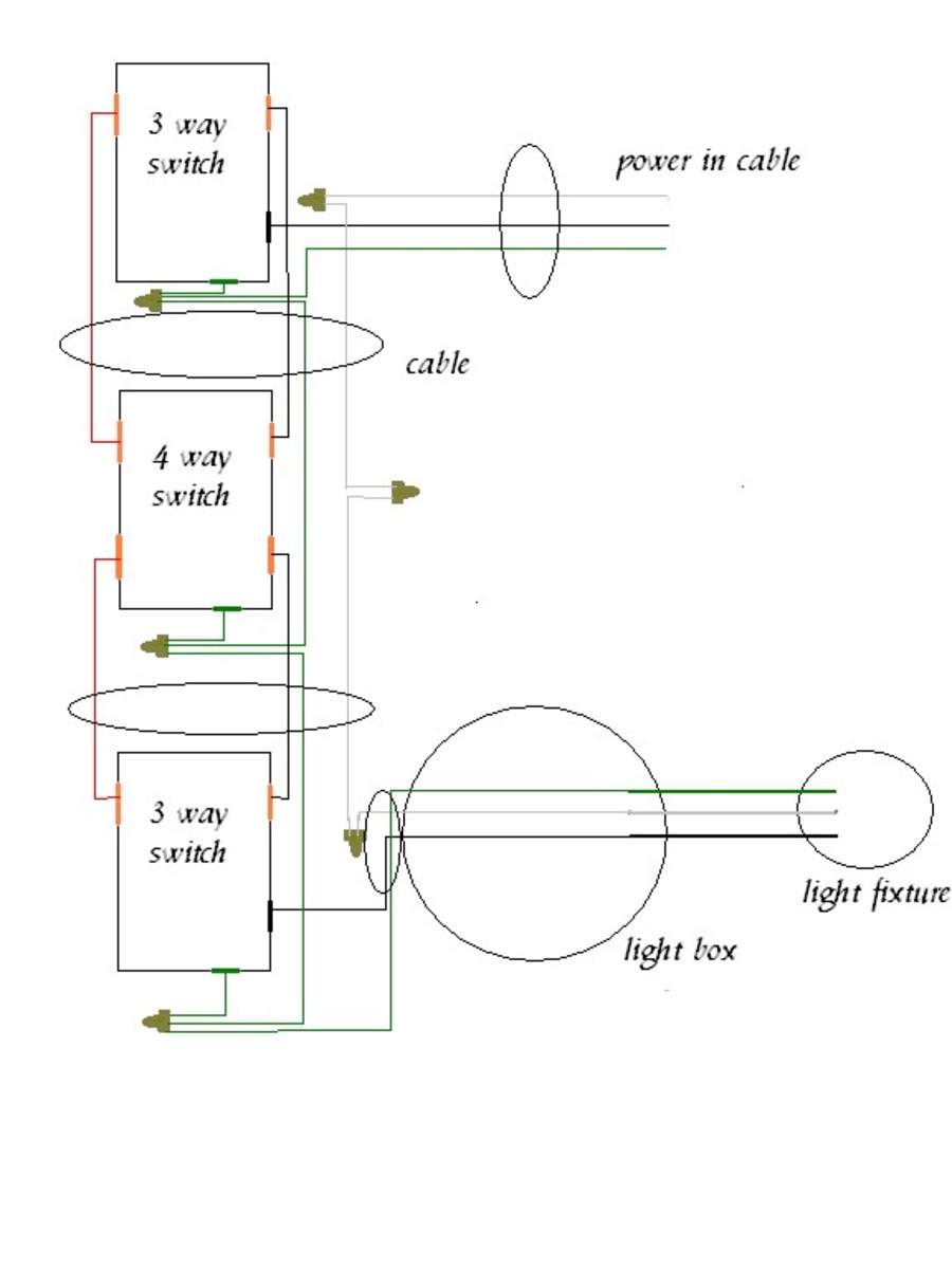
Security door controls ¡ www.sdcsecurity.com 4 1. Yamaha 703 remote control box wiring diagram. To make this circuit work, a 3 way dimmer can be used in place of one, or both of the standard 3 way switches.
You can download all the image about home and design for free. A wiring diagram is a streamlined standard pictorial representation of an electrical circuit. Phase 2 l1, l2, l3 ground, when used
Trailer wiring diagrams 4 way systems 4 way flat molded connectors allow basic hookup for three lighting functions. Control 4 wiring diagram general wiring diagram. These too would run off the brown or parking light wiring same as the license plate light.
Industrial control transformer wiring diagram. Control4 home automation wiring diagram. Mounting plate with four wires of the honeywell large dial thermostat model t87n1026.
Whelen control box wiring diagram. 4 typical wiring diagrams for push button control stations pilot light selection pilot light selection is based on the following factors; 4 wire trailer lights diagram.
Describe the meaning of the c13 in the diagram component q. Pin 30 is typically connected via a fuse to the positive terminal of the source. Powerflex 4m controller pdf manual download.
With the top diagram showing an air conditioning system and the second diagram showing a heat pump system and finally the third diagram. Describe the meaning of the 2 in diagram component s. Honeywell 4 wire thermostat wiring diagram.
Voltage, lamp requirements, environment, and cost.4 the voltage of a pilot light must match the voltage supply. Vintage air control wiring diagram. And the third diagram using clearance lights.
Mercury outboard control box wiring diagram. It installs in a standard back box using typical wiring standards and communicates to the control4 system using a wireless connection. As soon as the voltage is applied to the coil, pins 85 and 86 while pins 30 and 87 connect.
This is the wiring for a dimmer in a 4 way circuit. • dip switch settable 24v dc sink or source control for control wiring flexibility. If youre searching for any unique concept for your own parts diagram then the 4 3 tbi wiring diagram picture has to be on top of guide or you may use it for an alternative concept.
The load (lights, fan, etc.) is connected through pin 87 to the negative terminal of the power source. However your connections may seem a little different on the thermostat itself. The red (stoplight) wire must be connected to the cold side of the brake pedal stoplight switch.
As electrical panels are what will contain control systems, panel wiring diagrams are commonly encountered by plc technicians and engineers. Www.eaton.com technical data basic wiring for page 4 effective: Ceiling fan wiring diagram with remote control.
Frn 1 series, frn 2 series, adjustable frequency ac drive. All wiring must be reviewed and approved by the project engineer assigned to the location for its correctness and suitability for the application in which the equipment is installed andoperated. Understanding toyota wiring diagrams worksheet #1 1.
Control4 wireless thermostat installation guide and the control4 wireless thermostat user guide. The block diagram below highlights the primary.view and download allen bradley powerflex 4m user manual online. Describe the meaning of the s/d in diagram component t.
It shows how the electrical wires are interconnected and can also show where fixtures and components may be connected to the system. This post is called control 4 wiring diagram. 4 way dimmer switch wiring diagram.
A wiring diagram normally gives info about. An extra pin allows using another extra function. When and how to use a wiring diagram
How can you have two different voltages going into the same starter? The black wire is the power supply line to the brake control. Honeywell thermostat wiring diagram 4 wire source.
Describe and identify the diagram component u. Notifier cmx 2 control module wiring diagram. Standard diagram symbols td03309004e for more information visit:
Splice down line from the. A wiring diagram is a simple visual representation of the physical connections and physical layout of an electrical system or circuit. Wiring diagram what is a wiring diagram?
safety switch wiring diagram DHNX Wiring Diagram
safety switch wiring diagram DHNX Wiring Diagram

260z Ignition Switch Wiring Diagram Wiring Tech

4 Wire Ignition Switch Diagram Atv — UNTPIKAPPS
4 way wiring diagram Wiring Diagram and Schematics

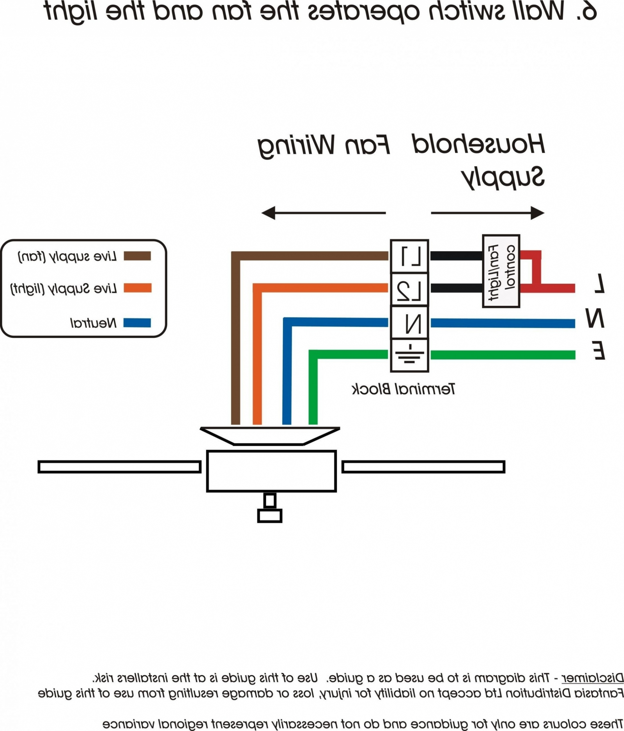
wiring diagram for 4 wire ceiling fan switch Wiring
4 Way Switch Wiring Diagram The Wiring

Telecaster 4 Way Switch Wiring Diagram Wiring Diagram

4 Prong 4 Pin Rocker Switch Wiring Diagram For Your Needs
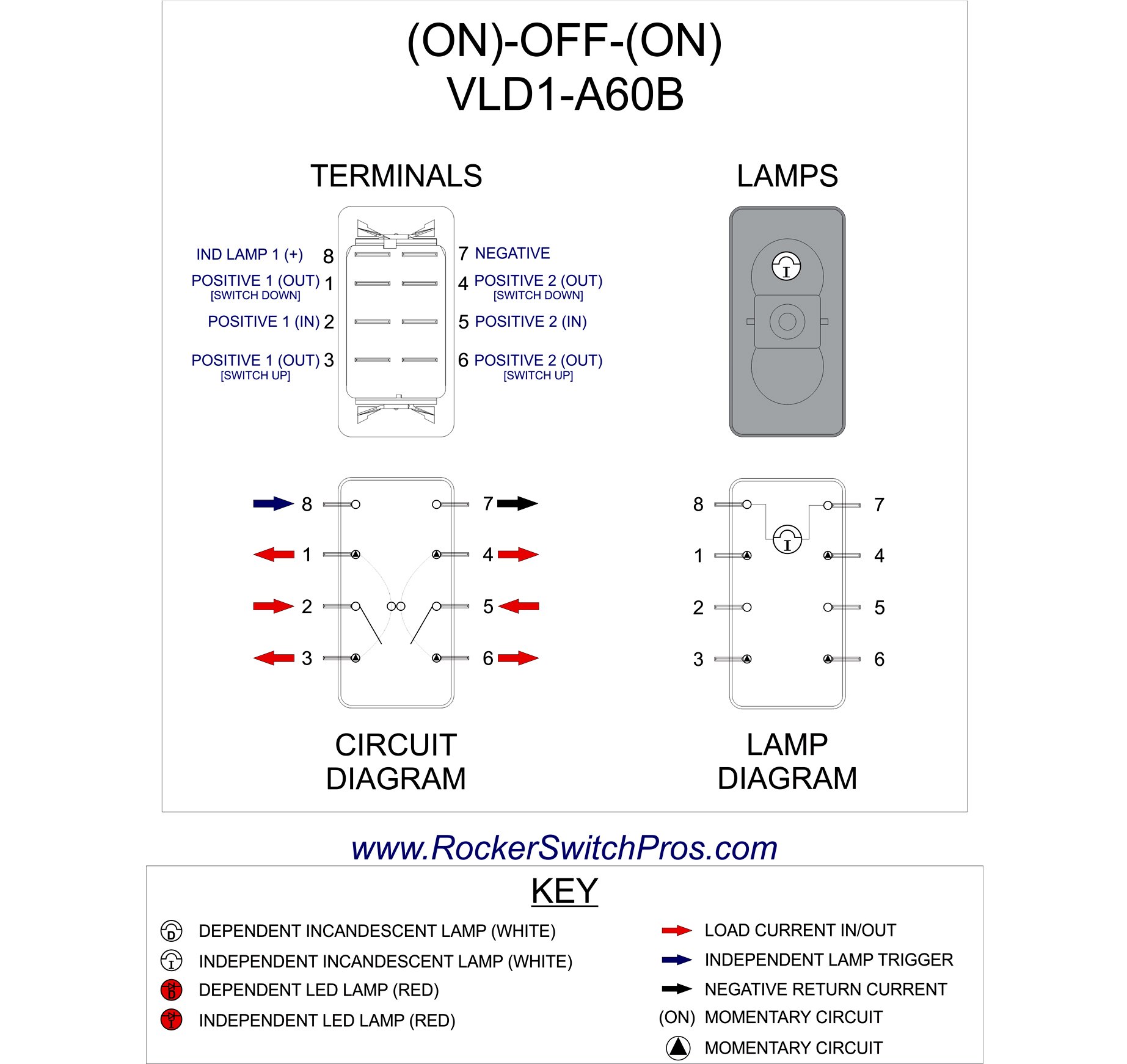
12v 4 pin rocker switch wiring diagram Wiring Diagram
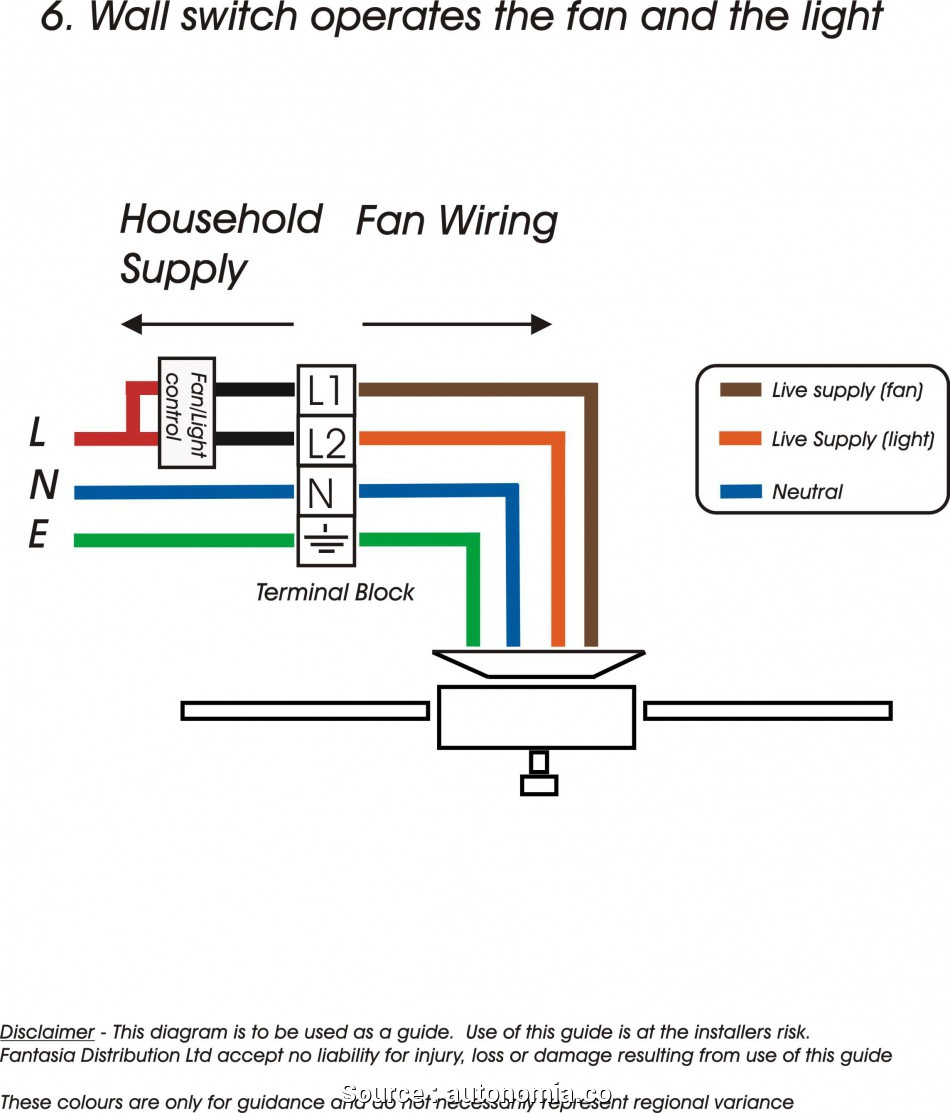
4 Wire Ceiling Fan Switch Wiring Diagram Wiring Diagram

4 Gang 2 Way Switch Wiring Diagram Wiring Diagram

Gallery Of Control 4 Wiring Diagram Sample

4 Way Switch Wiring Diagram The Wiring

4 Wire Switch Connection Wiring Diagram

12v 4 pin rocker switch wiring diagram Wiring Diagram
4 Way Switch Wiring Diagram Pdf Cadician's Blog
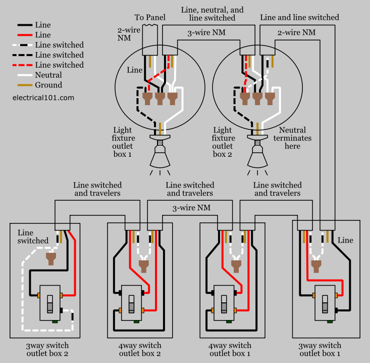
Alternate 4way Switch Wiring Electrical 101
Control4 Switch Wiring Wiring Diagram
