
Wiring diagrams and further information continues below. Danfoss randall can accept no responsibility for possible errors in.
Central Heating Wiring Diagrams Danfoss 3 Spring Return
Learn how to set your danfoss programmer/timer so it turns your central heating on and off automatically when you want it to.
Danfoss heating controls wiring diagram. This unit is the direct upgrade to replace the old fp715si programmer made by danfoss. Danfoss central heating wiring diagrams. Figure basic wiring schematic drawing.
Central heating wiring systems provides a comprehensive reference manual for hundreds of items of heating and control equipment, making it an indispensable handbook for electricians. Wiring diagram for tp5000 rt51 and rt52 tp5000 rt51 and rt52 a off b c com on nc no. Megavolt jan 20 danfoss hsa3 wiring diagram.
Figure adjustable frequency drive block diagram. Download file pdf wiring diagram danfoss. • on = the heating or hot water will remain on constantly • off = the heating or hot water will not come on • allday = the clock will turn the heating or hot water on at the first programmed on and will leave it on until your last programmed off h.
On danfoss fc302 wiring diagram. The actual climate of the installation site, the building’s energy requirements, the heating system, the type of operation etc. Tssi timeswitch no additional wiring diagram for the underfloor heating is required.
The diagrams below show typical wiring circuits with which the wiring conversionsto be used when replacing the following programmers with the fp cp. For a review on the fp720 and the improvements it makes on the old fp715si please have a look at our quick review blog post about the new fp720 heating timer and digital programmer by danfoss. Temporary override buttons the grey buttons next to the radiator are the heating override buttons (fig.18)
9 a turns of p e screw example a compressor is to be. The book provides comprehensive coverage of wiring and technical specifications, and Click the icon or the document title to download the pdf.
Download file pdf wiring diagram danfoss heating. Danfoss pressure switch wiring diagram. Feedback signals an important advantage to the cascade controller
Electrical wiring for central heating systemspart 3 in the series looks at y plan wiring a system which uses a single 3 port valve. A large display with intuitive layout shows current day, time and on/off period in the large top section, along with icons showing the status of the output channels. This diagram shows the wiring.
The vfds showed in the video are the d720s 230v single phase and the d720 230v three phase. Boiler wiring diagram for thermostat to y plan hive new unique drayton 22mm mid position valve wiring diagram Danfoss central heating wiring diagrams for more information see the 'danfoss wiring guide.'.
Danfoss central heating wiring diagrams for more information see the 'danfoss wiring guide.'. Learn the basic wiring of variable frequency drives vfd with our electrician steve quist. Contains all the essential wiring diagrams across our range of heating controls.
Services engineerthe hungry cyclistdomestic central heating wiring systems and controlselectrical installationspractical variable speed drives and power. Our wiring diagrams section details a selection of key wiring diagrams focused around typical sundial s and y plans. The cascade controller is effective in applications where multiple motors are used to control a common flow, level or pressure involving pumps, fans, and blowers.
Danfoss fp715si programmer wiring diagram. See our webpage on central heat. The cut in pressure is 3 5 bar and the cut off pressure is 5 bar.
The cut in pressure is 3 5 bar and the cut off pressure is 5 bar. The fp can be configured by the installer at time of installation to provide 7 day 24 hour or 5 day/2 day operation and to provide either 2 on/off's or 3. Read book wiring diagram danfoss.
To run sto, more wiring for the frequency converter is. The vlt® automationdrive fc /fc design. With over 75 years experience of producing pressure controls for industry applications danfoss offers the widest range of any manufacturer.
The book provides comprehensive coverage of wiring and technical Option card installs in the afd control card cassette and can be ordered factory installed. Danfoss wc4b wiring centre wiring guide danfoss wc4b wiring diagram.
Danfoss vfd control wiring diagram. View and download danfoss fp installation & user's instructions online. Both timers offer 1, 2 or 3 heating periods, whilst the fp720 also offers an additional channel for either time control of a hot water cylinder or 2nd heating zone.
Wiring diagram danfoss heating | e2b2bf54bce440eb2aceec4e05b6175c new applications of electric drivesindustrial refrigeration handbookthe electrical reviewheat transfer in food cooling applicationsdomestic central heating wiring systems and controlscentral heatinggas journalashrae The diagrams below show typical wiring circuit's with which the wiring conversionsto be used when replacing the following programmers with the fp, cp. Read book wiring diagram danfoss heating assessed in detail:
Domestic central heating wiring systems and controls drawing from the best of Standard cascade control wiring diagram. A variable frequency drive regulates the speed and operation of an electric motors.

heatmiser underfloor heating wiring diagram Wiring

Danfoss Randall 103 Wiring Diagram

Danfoss Wiring Diagram Central Heating Central heating
Danfoss 2 Channel Programmer Wiring Diagram

Central Heating Wiring Diagrams Danfoss 2 Spring Return

Howto easily set up a Danfoss FP720 heating timer Blog

Danfoss TPOneM Programmable Room Thermostat (Mains Powered)

Danfoss TPOne Programmable Room Thermostat Mains

Danfoss 3 Way Valve Wiring Diagram yazminahmed

Wiring Diagram For Danfoss Motorised Valve Wiring Diagram

heatmiser underfloor heating wiring diagram Wiring
Danfoss Fp715 Wiring Diagram
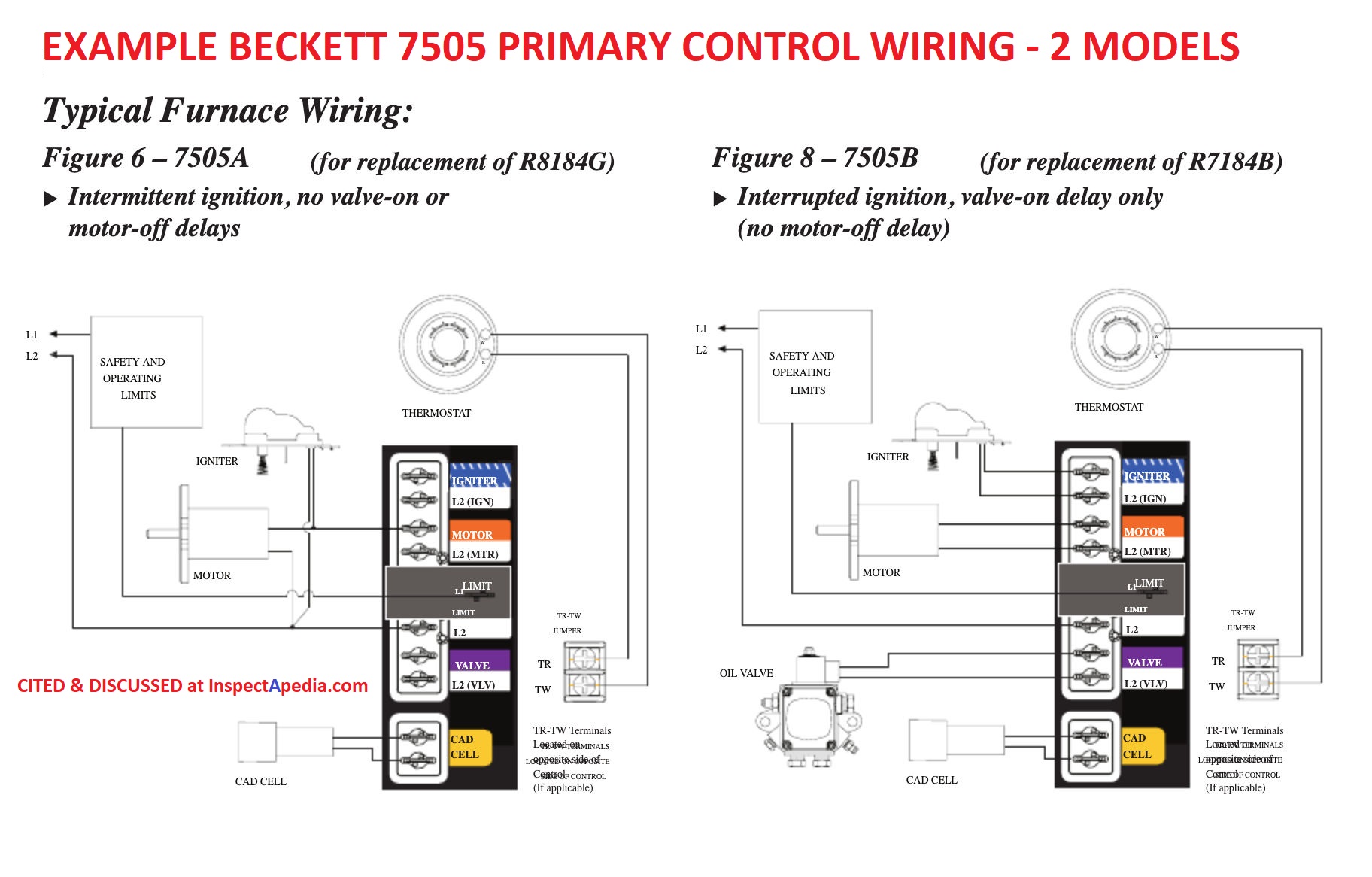
Oil Burner Control Wiring Diagram Wiring Diagram

Danfoss TPOne Programmable Room Thermostat Batteries
Central Heating Wiring Diagrams Danfoss 3 Spring Return


Danfoss Central Heating Heating Controls Plumbing

Oil Burner Control Wiring Diagram Wiring Diagram
Oil Burner Control Wiring Diagram Wiring Diagram
45 danfoss vfd with bypass wiring diagram diagram