Acme’s drive isolation transformers maximize the power quality benefits gained from standard isolation transformers by: The separate primary and secondary windings provide electrical isolation between the incoming line and the scr load.
![]()
Drive Isolation Transformer Wiring Diagram Wiring Diagram
If your mains voltage is higher, use an isolation transformer located between the power mains and the tq10 drive.
Drive isolation transformer wiring diagram. The wiring compartment should be easily accessible at all. Primary and secondary protection is required if the transformer has more than two wires on the secondary circuit. Acme uses one turn per layer of thin strip conductor which provides lower eddy current losses than comparable wire wound units.
Use the “find a product” tool on our website for detailed specification sheets. Dimensions (wxdxh) 26.00 x 25.00 x 38.00 : Cable connections while the transformer is energized.
Wiring diagram width depth height 20 te3a0020kg dh1 21.50 20.10 22.00 220 f or w* scd 9 27 te3a0027kg dh2 25.80 23.80 28.80 280 f or w* scd 9 All the transformers in this section are rated for both 50 and 60 hz, for use worldwide. Powered through the isolation transformer, the circuit with z1 and z2 no longer shares earth ground with the generator and oscilloscope.
To ensure compatibility, check the wiring diagram by clicking a part number and viewing its product page. General purpose distribution transformers are not adequate for this type of application. Now connecting the test probe at tp1 and the probe ground at tp2 does not complete a circuit and voltage v1 can be measured accurately.
Your isolation transformer should be insulated to ~2300v rms. The difficulty in point of fact is that all car is different. Lower losses = cooler operation and longer transformer life.
Refer to wiring diagrams for details. Termination front accessible separate high and low voltage terminations; Visit our website at www.solaheviduty.com or.
The transformer must also provide a voltage change to match the required voltage of the scr drive. In the same way as a pain to remove, replace or repair the wiring in an automobile, having an accurate and detailed. The acme drive isolation transformers are specifically designed to handle the mechanical stresses, voltage distortions, and harmonics associated with ac and dc variable speed drives.
Using an isolation transformer the tq10 drive’s mains voltage is limited to 120 vac nominal. Attach or remove the tq10 drive’s power plug only while input power is off. The thicker the winding conductor, the greater the losses.
First start the isolation transformer without load to observe and test whether the input and output voltages meet the requirements. In the diagram above, taking an installation without an isolation transformer, the device has an earth fault (for example a live conductor has shorted to the chassis). Hps drive isolation transformers are designed to meet the rugged demands of both ac and dc variable speed drives and also.
F or w * case style: The circuit in figure 2 uses an isolation transformer. Understanding the design basics of isolation transformers technical articles.
What is a drive isolation transformer? Check the i/o line to make sure the wiring being accurate. Suitable for copper and aluminum are provided for easy cable installation.
If the branch circuit feeding the transformer has overcurrent protection to meet the individual protection requirements in example 1, then individual transformer protection is not required. Dimensions (wxdxh) 39.50 x 34.00 x 51.50 : Drive isolation transformers are sized to match standard motor horsepower and voltage ratings.
Select a transformer that will operate on the supply voltage available at your facility (example: Purpose of shielded isolation transformer. To maintain safe operating conditions, do not remove the panels or cover while the transformer is in operation.
The separate primary and secondary windings provide electrical isolation Drives increase eddy current losses (heat) in transformer windings. Use of a solidly grounded drive isolation transformer to reroute i scientific diagram.
Use the “find a product” tool on our website for detailed specification sheets. Drive isolation transformers are designed for scr (silicon control rectifier) variable speed motor drive applications where a transformer is needed to magnetically isolate the incoming line from the motor drive. The ground wire is connected to the transformer housing (if the transformer has a case, it should be connected to the ground wire of the case).
Hps drive isolation transformers are designed to meet the rugged demands of both ac and dc variable speed drives and also to provide the required voltage change. Since neutral and earth are bonded in the consumer unit the system sees this as a short circuit and so a large current will flow which will blow the fuse or trip a circuit breaker. Hammond’s drive isolation transformers are designed to meet the rugged demands of both ac and dc variable speed drives and also to provide the required voltage change.
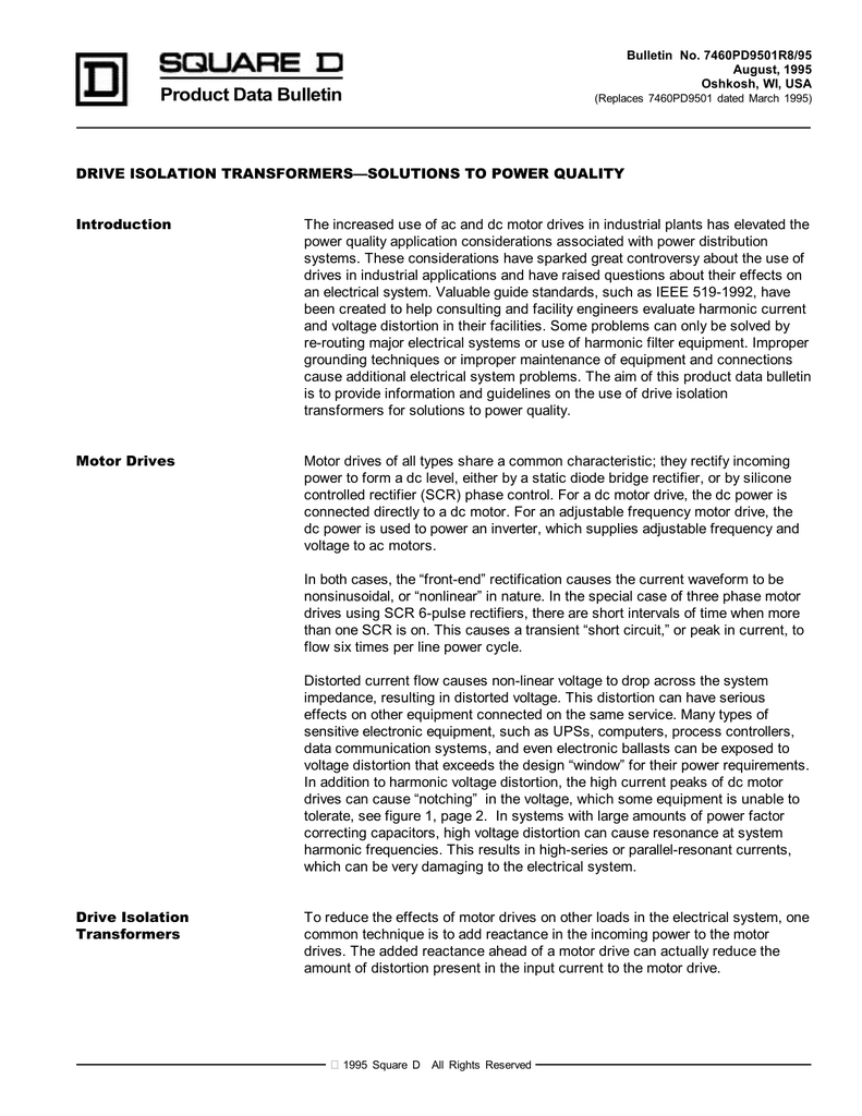
Drive Isolation TransformersSolutions to
Isolation Transformers Reduce Drive Neutral Point Voltage

Isolated Ground Transformer Wiring Diagram Wiring Diagram

Pin on Solar Power and Sensor Based
Know More about Electrical Isolation Transformers and Auto

How do drive isolation transformers differ from line reactors?

Isolation in Digital Power Supply—Why and How LEKULE BLOG
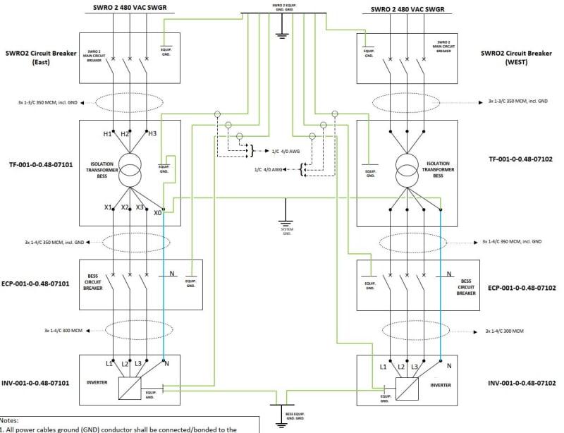
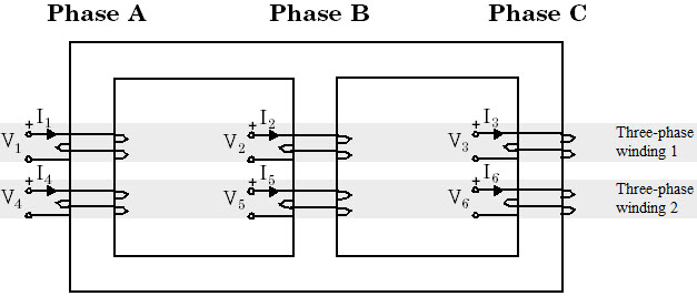
Three Phase Isolation Transformer Wiring Diagram

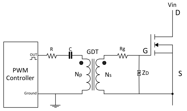
Gate drive transformer vs. high/low side driver Which way
![]()
Drive Isolation Transformer Wiring Diagram Wiring Diagram
![]()
Why Use an Isolation Transformer? Voltage Disturbance
![]()
How do drive isolation transformers differ from line reactors?
![]()
Drive Isolation Transformer Wiring Diagram Wiring Diagram
![]()
Use of a solidly grounded drive isolation transformer to

Isolation in Digital Power Supply—Why and How LEKULE
![]()
Drive Isolation Transformer Wiring Diagram Wiring Diagram
![]()
DRIVE ISOLATION TRANSFORMERS L/C
![]()
DRIVE ISOLATION TRANSFORMERS L/C
Why Use an Isolation Transformer? Voltage Disturbance