
This appears to be available from bmw or walloth. E1 e2 e3 e4 7.
220 Volt Relay Wiring Diagram

If someone is sufficiently motivated it could be recreated with modern logic and a relay.
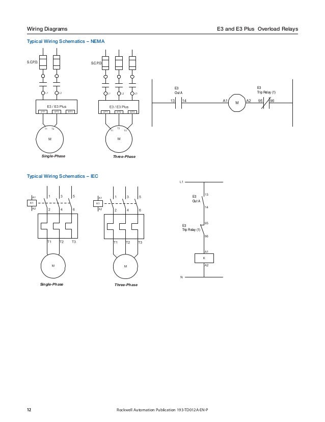
E3 plus relay wiring diagram. This is all very clear from examining the wiring diagram found in the factory blue binder. Brown wires are usually ground; Added ams & amt ‘basic’ meters.
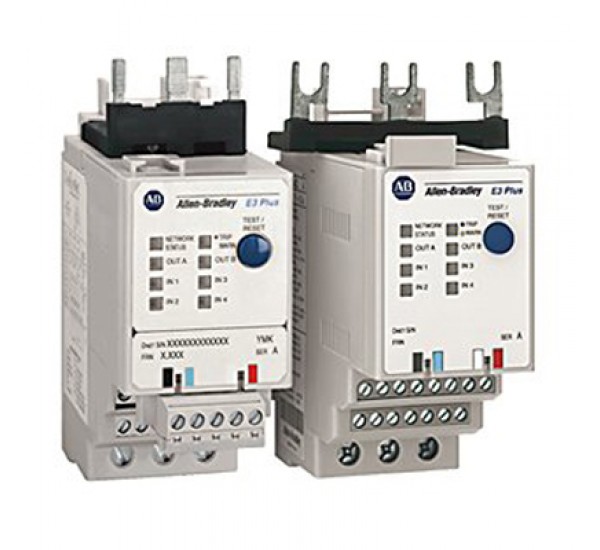
† e3 overload relay as it applies to both the e3 and e3 plus overload relays. “e3” is the standard version. Plus, you can use it wherever you are—smartdraw runs on any device with an internet connection.
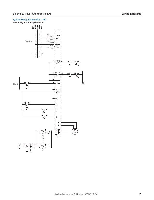
Conventions parameter names are shown in italic typeface. Table 2.1 tricon e/e2/e3 wiring codes figure 2.5 tricon/e/e2/e3 wiring 1the (+) indicates conventional current exiting the tricon. Learn what some of t.
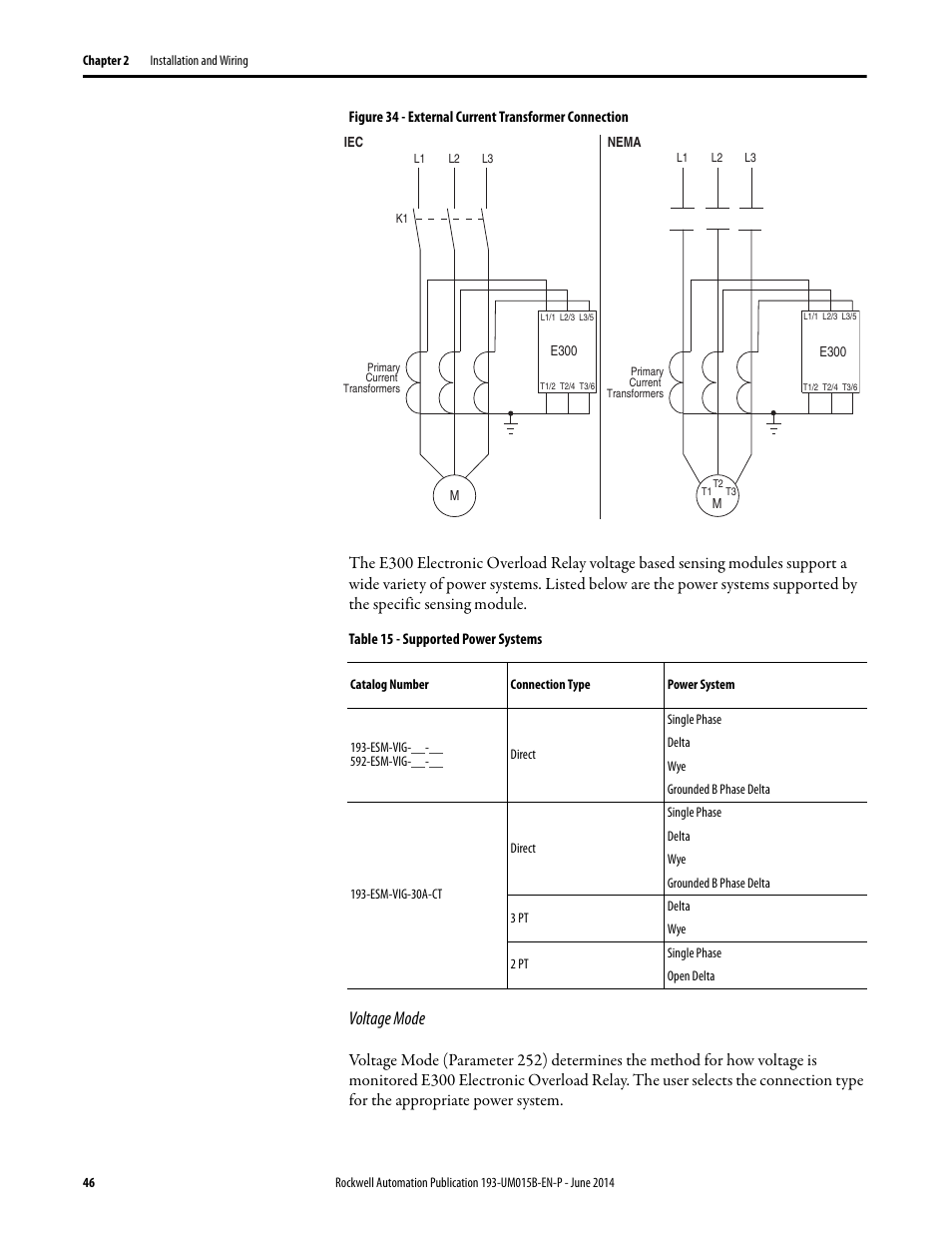
Removed references to p1 meter. For the e300 electronic overload relay to function. The design provides an integrated din rail mount and panel mounting holes and is intended for the following aplications:
As shown in the figure, the sensorless homing function can be used to connect the corresponding axis with the jumper cap. Begin with the exact wiring diagram template you need for your house or office—not just a blank screen. Customers are encouraged to migrate to the e300 electronic overload relays coupled with the new devicenet or ethernet/ip communication module.
When working on energized circuits, do not rely on the voltage and current information provided by the e3 and e3 plus for personal. Can anybody explain how the e3 (or e3 plus) relay gets control power? Relays 9 6 j1 trip 5 j6 5 4 tb1 10 x2 run 1 program jumper 2 phase b 4 tb2 alarm 1 6 4 12 time delay no nc lock out a2 6 7 9 ci grn 10.
Complete the device wiring according to the appropriate wiring diagrams for your application. Download 3d printing product manuals, firmware, software, software upgrades, etc. † e3 plus overload relay when features and/or functions apply specifically to it.
If it is, then what happened when devicenet is not connected to the relay? Cyo e premium headlight not working with my new izip e3 vibe plus a serfas true rechargeable headlight on my bike (in the same place), so, short of dismantling the motor and wiring harness, i've tested.24 volt battery pack wire harness for currie, ezip, izip & schwinn electric scooters: The wiring diagrams in this section are for illustrative purposes only.
If you select this feature, you cannot use external endstop!! Expanded description of l&g’s em1210 to include the amj. “e3 plus” is the enhanced version.
For more information, see the e3/e3 plus to e300/e200 electronic overload relay migration profile. Smartdraw's wiring diagram software gets you started quickly and finished fast. Wiring diagrams 12 approximate dimensions 14 resource description.
New dimensions, wiring, and panel layout are all dreaded parts of legacy product replacement. Afterward irritating to remove, replace or fix the wiring in an automobile, having an accurate and detailed creality ender 3 wiring diagram is vital to the. • the ptc thermistor cable shield shall be grounded at the e3 plus overload relay with no connection made at the opposite end wiring diagrams figure 5:
E3 refers to the overload relays e3 and e3 plus. The harness is then just a matter of laying things out, scoping out the correct connectors and making it. You should be looking for wiring colours and functions to confirm the wire is original.
Brett will discuss the migration of the e1plus to e100 electronic overload relay and the e3 plus to e300/e200 electronic overload relay. If you select this feature, you cannot use external endstop!! I am looking into the schematic and wiring diagram of a motor starter and don't see any control power connected to the e3 plus relay.
What you don't want is. Th e compact enclosure is optimized to run wires under the back panel and thru the knockouts shown in figure 3.1 and figure 3.2. Improved protection is delivered as thermal
You can check with continuity tester. The rhd wiring diagrams should cover many of the areas in question. With eet, added rom relay (new), added amz to amx section, removed iskra me372 and mt372 sections.
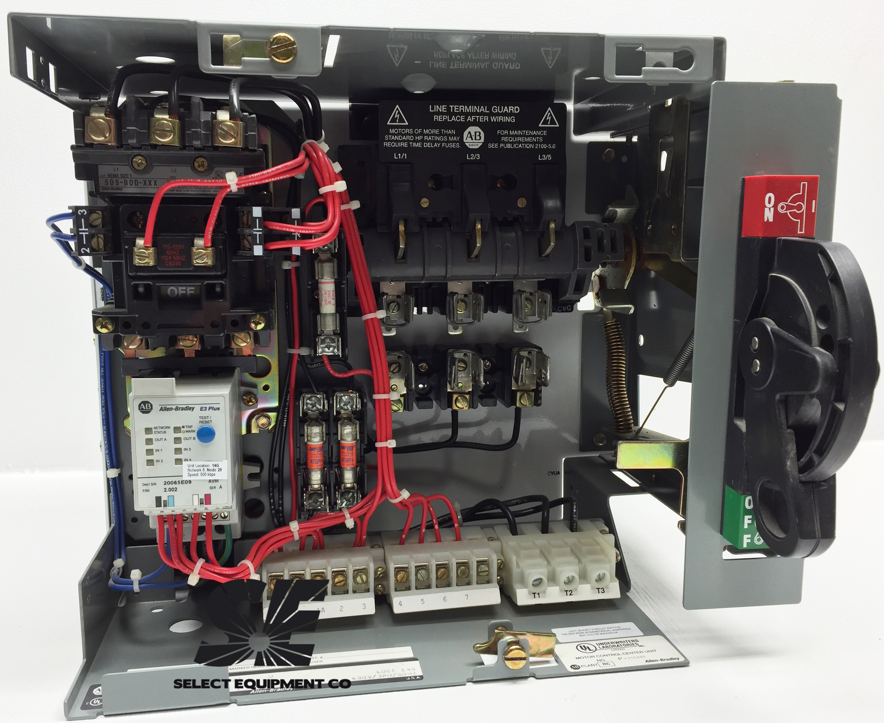
Our bulletin 193 iec and 592 nema e3 and e3 plus electronic overload relays are discontinued and no longer available for sale. In rok talk on industrial components episode 3, amanda eason describes how you can replace an e3 plus with the e300 in 3 easy steps. Www.linearcorp.com 5 e3 emerge installation instructions 3.0 installing the control panel 3.1 mounting the compact enclosure th e housing is designed to accommodate the necessary wiring connections for most installations.
Sensorless homing function selection: as shown in the figure, the sensorless homing function can be used to connect the corresponding axis with the jumper cap.
193EC1CB Allen Bradley E3 Overload Relay Select
193 td012 enp
What is your cost for unplanned electric motor downtime?

Nordyne Air Handler Wiring Diagram General Wiring Diagram

สินค้าอุตสาหกรรม E3 and E3 Plus Electronic Overload Relays
Blog Archives cowbackuper

193, 193S E1 Plus & E3 Plus Solid State Overload Relay

New Allen Bradley 193EC2CD /C E3 Plus Solid State
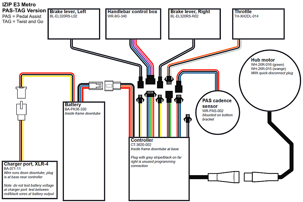
IZIP E3 Metro Men's Electric Bicycle Parts
193 td012 enp
E300 Overload Relay Wiring Diagram Wiring View and

Allen Bradley 193NCEC5CNT Replacement Cable and Connector

AllenBradley 193EPRB Revere Electric Supply

Allen Bradley 193EC3PB E3 Plus Electronic Motor

Allen Bradley 193EC3PB E3 Plus Electronic Motor
52 F350 Trailer Plug Wiring Harness Diagram

193EC1AD E3 15 A Overload Relay Images

![]()
51 E300 Overload Relay Wiring Diagram Wiring Diagram Plan

Allen Bradley 193EC3AB /C E3 Plus Electronic Motor