
There are lots to handle with this device and it can be quite difficult. Finding the model of your fireplace, stove or insert.
Fireplace Blower Wiring Diagram Fireplace World
Heatilator fireplace insert parts heatilator fireplace doors 36 insert parts scientificredcards org heatilator gas fireplace blower not working manual replacement.

Heatilator gas fireplace wiring diagram. Rc 300 intellifire plus wireless remote; This appliance must be electronically wired and grounded in accordance with local codes, or in the absence of Radiation shield (a).fit perfect in my heatilator gas fireplace insert.
Materials that are reported as passing astm e 136, 2 x 4 or 2 x 6 header drywall 3 in. How to clean the glass on a gas fireplace;
These are designed to be replacements for the listed blower model number. Such materials are those consisting entirely of steel, iron, brick, tile, concrete, slate, glass or plasters, or any combination thereof. That the sensor wire is not shorted.
The wires from the nest thermostat should be connected to terminals 1 and 3 on the relay. Gas and wood burning fireplaces have a rating plate in the control compartment area, under the smoke shield or on the firebox side column. (203 mm) extra space needed (both sides) for outside air connection.
Installation and service must be performed by a qualified heatilator, a brand of hearth & home technologies standing pilot ignition wiring diagram. Figure 9.14 proper positioning and. No combustible framing to be located within shaded area.
Put those on all of the wires, including two wires from the nest and the two in the fireplace. Using a screw driver, connect the red wire to the “r” terminal, the yellow or white wire to the “w” or “y” terminal, and the green wire to the “g” terminal. 30 1/2 in.* (772 mm) 61 5/8 in.
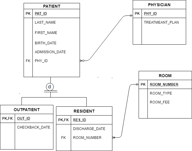
The diagram shows 120v coming into a 120v24v transformer and. Find your heatilator product installation or owner’s manual. Connect terminals 2 and 4 on the relay to the thermostat that leads from the fireplace.
Gas fireplace wiring diagram wiring diagram is a simplified up to standard pictorial representation of an electrical circuit. 1 suction 8,1 mm 2 service 8,1 mm 3 discharge 6,5 mm made by huayi for danfoss technical data sheet gp12te printed on 13/03/18 4/5. Locating your heatilator model and serial number;
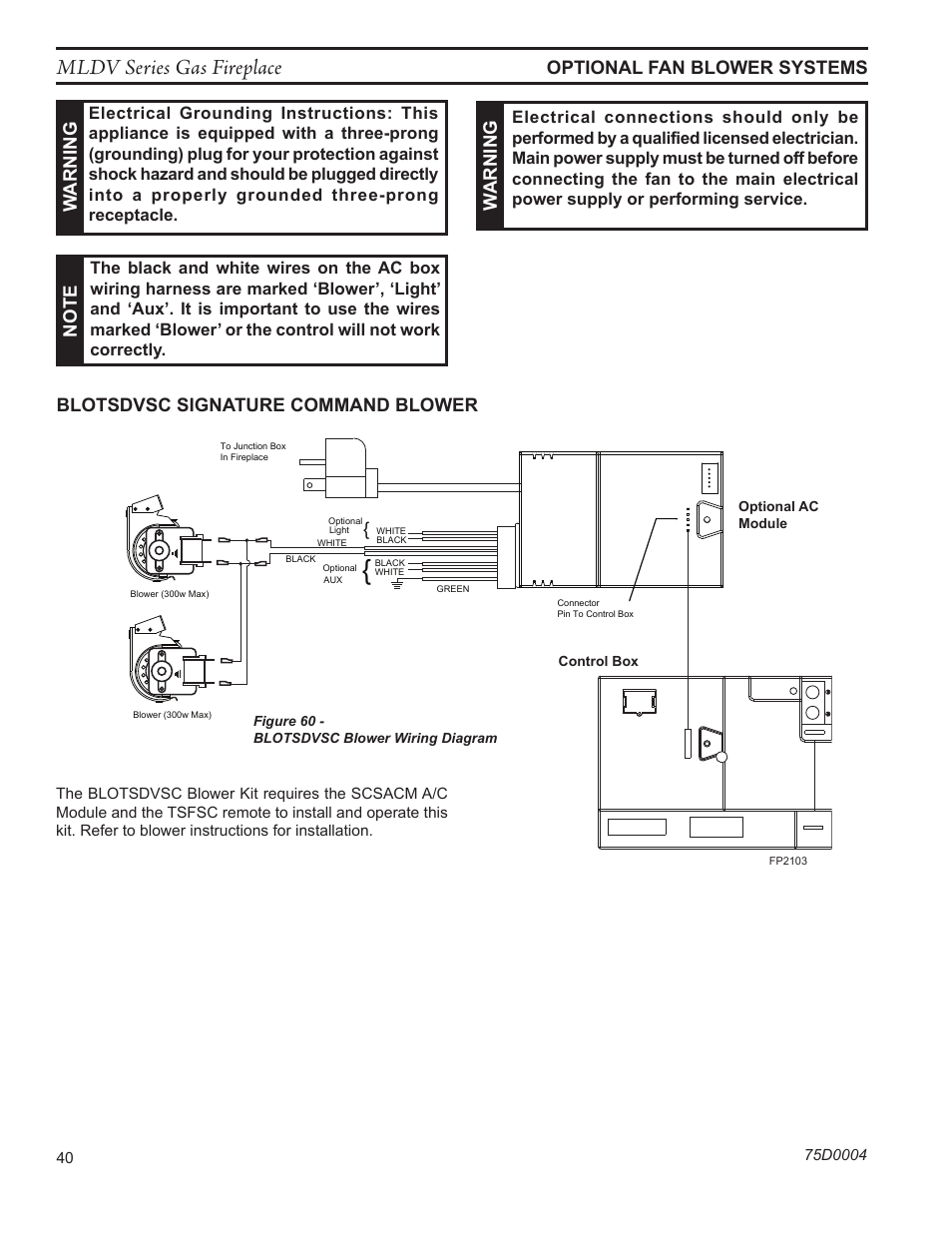
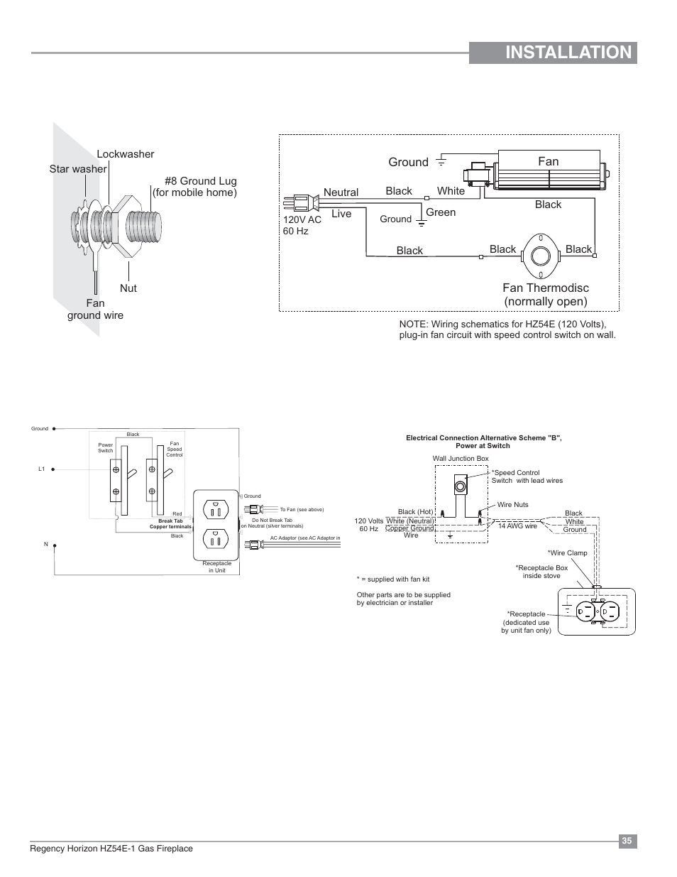
The junction bos is wired for the fireplace ignition, yet the fan outlet is not wired. How should i extend the wiring to the fan receptacle, since there is one black and white wire entering the junction box. Standing pilot wiring diagram figure 3.
B4) figure b5 illustrates the fan and control module positioning. The video walks through the simple steps on starting and operating a gas fireplace. The junction box is controlled by one switch on the wall.
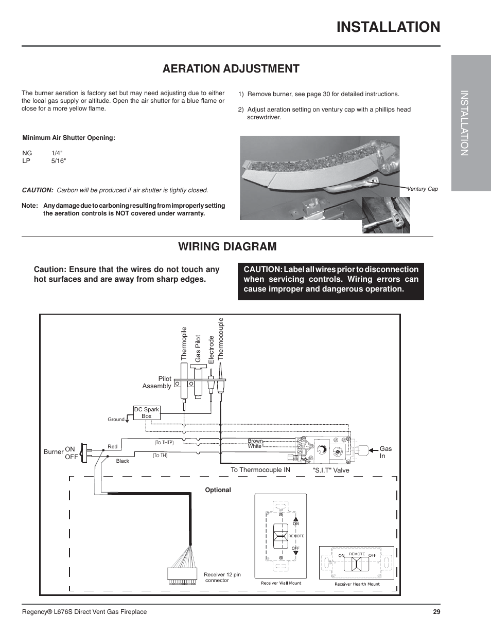
3 useful things to learn from heatilator gas fireplace manual. Check with your local gas utility to determine proper orifice size. Wiring diagrams and electrical assembly csir connection (l, p ranges) designation internal diam.
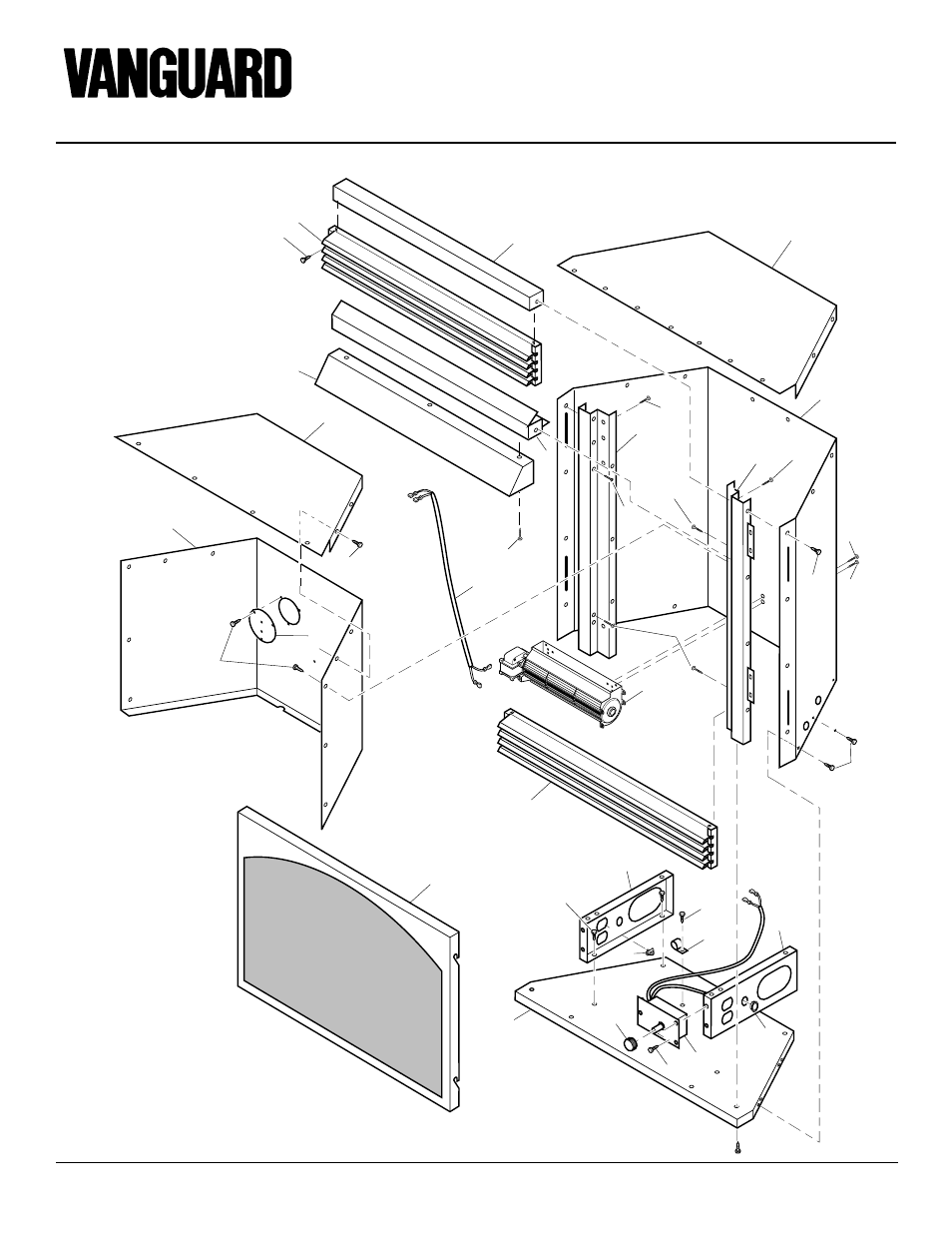
Diagram below shows parts required, from fireplace carton. 6000c/8000c & ipi latin american spanish. It covers start up, flame & heat output and fan adjustment.
Pellet stove convection blower for england stove works. Type:vented gas fireplace heater standard: Each fireplace and insert has a rating plate which contains your model number and serial number.
Then may be fine for awhile. I bought and attached some 1 wide by 5/16 thick weather stripping to dampen the noise and then velcro hook and loop to the weather stripping to attach the blower to the back of the insert. I have a heatilator fireplace and i am installing an internal fan.
Whether you need tools for design, installing, or servicing one of our products, our selection of heatilator manuals and downloads have you covered. If outside air duct has no bend, this dimension may be reduced as. My heatilator gas fireplace has an intermittent problem.
8 steps to install a heatilator gas fireplace. (13 mm) minimum to perpendicular wall. 8000 series gas fireplace ul listing:
Each fireplace and insert has a rating plate which contains your model number and serial number. For those familiar with the heatilator product line, you’ll likely be using this resource often, and we’re okay with that. The following wiring diagrams are for illustration purpose only.
B3) step 4) ground ring terminal end of green wire connected to fan onto metal frame of fireplace. Intellifi re (ipi) wiring diagram to the electrical junction box and through a provided or approved strain relief.

I have heatilator fireplace model GCDC60E with a
Warning, Step 8. wiring the fireplace, For intermittent

Wiring Diagram Ga Fireplace Wiring Diagram Schemas

I have a heatilator 36 ebu electric fireplace which is not
Fireplace Blower Wiring Diagram Fireplace World


Heatilator Gas Fireplace Wiring Diagram Fireplace World
Heatilator Gas Fireplace Wiring Diagram Fireplace World

Heatilator GCDC60 Indoor Fireplace Installation

Heatilator Parts Diagram

Heatilator Gas Fireplace Wiring Diagram Food Ideas
Heatilator Wiring Diagram

Heatilator Parts Diagram
Wiring Diagram Gas Fireplace IDOPKUXTENTERAM
Wiring Diagram For Ga Fireplace Wiring Diagram Schemas

Gas fireplace malfunction Community Forums

Heatilator Parts Diagram

I have heatilator fireplace model GCDC60E with a
Gas Fireplace Parts Diagram Wiring Diagram
Wiring Diagram Ga Fireplace Wiring Diagram Schemas
