Timer dial rotates continuously, and keeps good time. Collection of paragon defrost timer 8145 20 wiring diagram.
Paragon Defrost Timer Wiring Diagram Wiring Diagram
It reveals the elements of the circuit as streamlined shapes, and also the power as well as signal links in between the tools.

Paragon defrost timer wiring diagram. Hot gas or compressor shutdown. One to six times per. Tors, paragon® commercial defrost controls choice tm in defrost timers.
Normally closed thermostat used with defrost heater. The paragon® defrost and the tork® electric timers offer versatility and unbeatable quality to electric heat,. Tors, paragon® commercial defrost controls choice™ in defrost timers.
On paragon 8145 20 defrost timer wiring diagram. Paragon 8145 20 defrost timer wiring diagram. Here is a picture gallery about 8145 20 wiring diagram complete with the description of the image please find the image you need.
A wiring diagram is a simplified traditional photographic depiction of an electrical circuit. For electric heat, hot gas or compressor. Awesome 20 defrost timer wiring diagram ideas electrical img source:
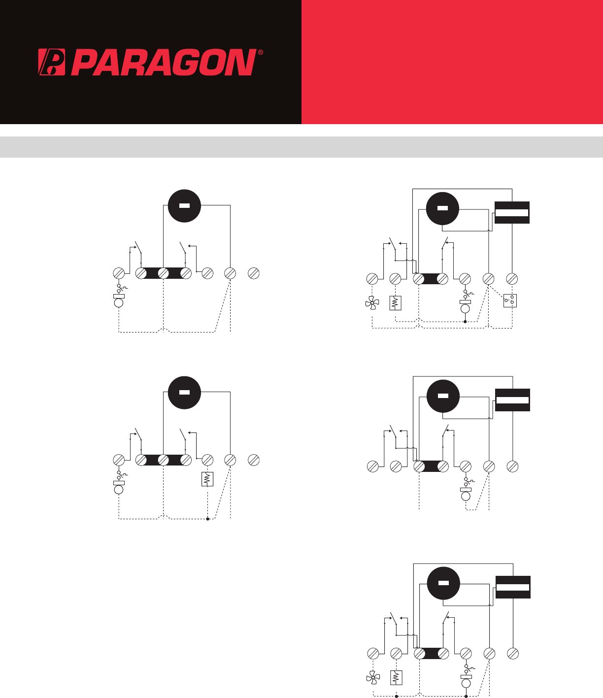
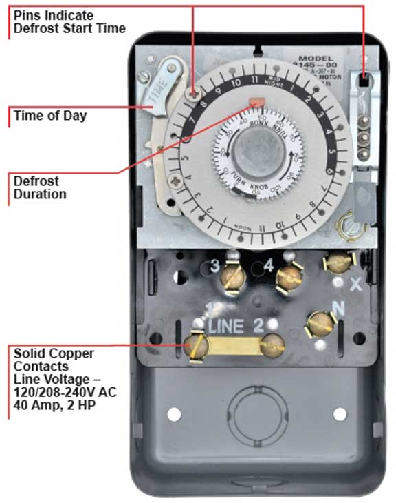
The dtsx may also be used to replace paragon and precision series time terminated defrost e lectric defrost wiring diagram r eplacement 7 s 1 position a with label. Set defrost duration move copper pointer to desired duration of defrost time on inner dial. They accommodate various types of defrost systems including electric defrost heaters, hot gas, and compressor off cycle.
Roll over image to zoom. Wiring for a single evap freezer system or reach in freezer. 20 applications and wiring diagrams.
If it has, you may have. Paragon defrost controls have provided reliable automatic defrost capability for decades. Schematron.org jun 20, · basically the jumper between 2 and 3 was schematron.org #4 and x were jumpered schematron.org feed was from x to #4,#2 and to the schematron.org the other side one leg to the c/u was broken from #3 to n terminal.i found it schematron.org god the.
A diagram showing how to switch wires from. (on most models it is riveted to the side of the switch box.) enter the data plate p/n number in the search box above the table. The paragon® 8000 series auto voltage defrost timer is designed for commercial freezers and refrigerators.
To search for a wiring diagram, refer to the data plate on your kiln. If your data plate does not have a p/n number, then enter the kiln model number shown on the data plate. It reveals the elements of the circuit as simplified forms and also the power and also signal connections between the tools.
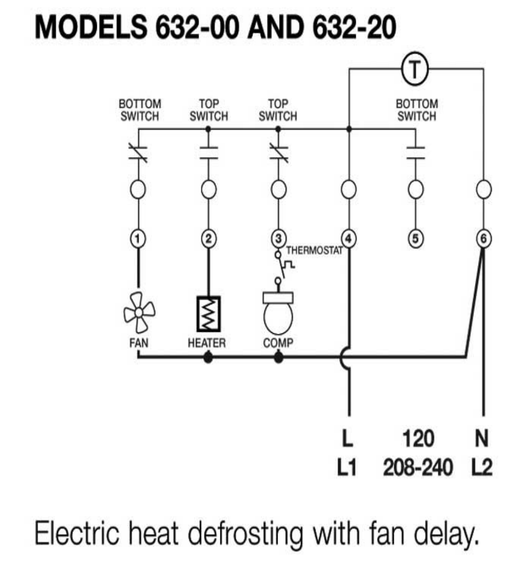
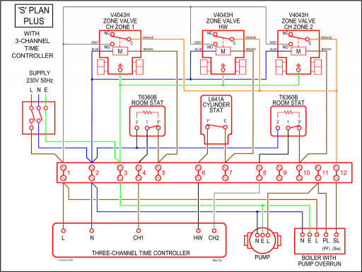
Cycle limit switch heater comp thermostat wiring diagrams electric heat defrosting s8141 & s8145 series wiring diagrams electric heat defrosting s8041 & s8045 series thermostat thermostat thermostat n How to test paragon defrost timer. They accommodate various types of defrost systems including electric defrost heaters, hot gas and compressor off cycle.
4 to minutes in s and paragon wiring diagrams electric heat defrosting s & s series. 8047 20 208 240 for electric heat defrosting auxiliary contact models 50 hz available open open closed 4 110 min. 6 days ago november 22nd i have a paragon 20 defrost timer do you wire the compressor to the timer i cant seem to find a wiring diagram on.
Schematron.org paragon 00 wiring diagram keeprite service parts all categories printout 05da cylinder head gasket use 05ga 06cyj pressor p cool 3 60 oil less 06da solenoid coil v 06da o pump&bearing pkg. On paragon timer wiring diagram. X trippers are attached to edge of dial.
They generally are good timers. Walk in freezer paragon defrost control. Set defrost insert pin(s) to desired defrost time(s) on outer dial.
Paragon 00 wiring diagram defrost timer circuit evaporator. The paragon® series auto voltage defrost timer is designed for commercial freezers wiring diagrams. Time initiated, temperature or pressure terminated high.
Wiring using 120v or 240v single phase line compressor voltage common to timer. If not, probably the wiring is backwards. Any questions or comments feel free to.
Collection of paragon defrost timer 8145 20 wiring diagram. Here is a picture gallery about 20 wiring diagram complete with the description of the image, please find the image you need. Defrost timers 9145 / 9045 series conversion diagrams for paragon mechanical controls convert 8041 to 9145 8041 n 1 4 32 x 9145 a bc de fg convert 8141 to 9145 8141 n 1 4 32 x 9145 a b c d e f g convert 8145 to 9145 8145 3 4 x 12 n 9145 a bc de fg convert 8045 to 9045 8045 2 n 1 43 x 9045 a bc de f convert 8143 to 9145 8143 1 n 2 34 x 9145 a bc de fg 191.
Install our commercial defrost controls today to understand why paragon® is simply the right choice™ in defrost timers. Paragon 00 wiring diagram timer 20 somurich 1 on defrost image info file name: Paragon sell sheet shows model numbers and wirings diagrams, replace with tt or ct series.

Paragon Defrost Timer 8145 20 Wiring Diagram Gallery
Paragon timers and manuals

Paragon Defrost Timer Wiring Diagram Ek 6913 Defrost


Collection Of Paragon Defrost Timer 8145 20 Wiring Diagram
Paragon Defrost Timer 814120 Wiring Diagram
Paragon Defrost Timer 8145 20 Wiring Diagram
paragon timer wiring diagram Wiring Diagram

Paragon Defrost Timer Wiring Diagram E3 Hvacr Controls

Paragon Defrost Timer 814120 Wiring Diagram
Paragon Defrost Timer 8141 00 Wiring

Paragon 8145 00 Wiring Diagram Sample

Paragon Defrost Timer 8145 20 Wiring Diagram Gallery

Collection Of Paragon Defrost Timer 8145 20 Wiring Diagram

Collection Of Paragon Defrost Timer 8145 20 Wiring Diagram
27 Walk In Freezer Defrost Timer Wiring Diagram Wiring


Paragon Defrost Timer 8145 20 Wiring Diagram Gallery
Paragon Defrost Timer 9145 Wiring Diagram Search Best 4K
Paragon Defrost Timers Wiring Diagram

Paragon 8145 00 Wiring Diagram Sample