
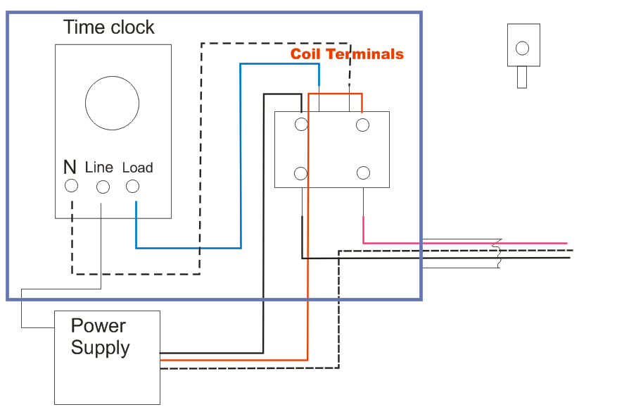
Put the time clock contacts after the photocontrol in series with the red lead. Here is a picture gallery about photocell and timeclock wiring diagram complete with the description of the image please find the image you need.

Photocell Lighting Contactor Wiring Diagram Elec Eng World
Lighting contactor wiring diagram ditdottudit.

Photocell on time clock off wiring diagram. Basically the timer will supply the power to the photocell and then at a certain time(lets say midnight) the timer switches off thus cutting power to the photo cell and so turns the lights off the next day the timer will switch on at a time when still daylight thus supplying power to the photocell and when dark enough will activate and turn the lights on Photocell and timer switch wires each have a line (black), load (red), neutral (white), and ground (green). Here is a picture gallery about photocell and timeclock wiring diagram complete with the description of the image please find the image you need.
Photocell and timeclock wiring diagram. I have 3 lighting feeds and one 3 core to the photocell, the time clock is to be. You may be in a position to learn precisely when the projects needs to be accomplished, which makes it much simpler to suit your needs to correctly handle your time.
Lighting, contactors , time clock and photo cell. The load side of the photocell is connected to 1. In operation, photocontrol turns on the lights at dusk (time clock is already on) then the time clock turns them off at 3am.
So when the photocell turns on, it disconnects the time clock output and here is the schematic for your application, minus the power. Set the time clock to the start and finish time you would want the lights to come on/off and the photocell will only turn the lights on when it is dark. Last the photocell output should be connected to the relay's coil.
As an example, set timer for on at 5pm and off at eleven. 3405a single wiring with diagram timer phase contactor. Photocells timers electrical 101 in photocell and timeclock wiring diagram image size 360 x 400 px.
Set the time clock to come on during daylight and off at 3am. Wire the photocell from the time clock and then from the photocell to the lights. The photocell is constantly powered on the line side.
Last the photocell output should be connected to the relays coil. Otherwise the structure will not work as it should be. Photocontrols need to be hot all the time.
Hit the timer first then the photocell. According to earlier, the traces at a photocell wiring diagram represents wires. 20a clm lighting contactor typical photocell 2w acc · 20a clm lighting contactor.feb 09, · photocell with timer and contactor wiring, photocell with timer wiring diagram, time clock photocell.
Photocell on time clock off wiring diagram. 57 bel air wiring diagram pdf. No neutral to timer or contactor.
Photocell and timer wiring diagram 1. However, it doesn’t mean connection between the wires. The line terminal of the time clock.
The photocells usually turn the lights on for a short time when power is applied to them which may be an issue. So when the photocell turns on, it disconnects the time clock output and energises the lighting contactor. 2 2.2 va max per relay to allow up to 20 relays to be controlled in parallel using class 2 wiring.
Lamar, it looks like you want to do this project after all. Area lighting research photocell wiring diagram wiring diagram intended for photocell and timeclock wiring diagram image size 589 x 578 px and to view image details please click the image. Contactor(s) coil(s) that run dusk to dawn lighting (selected fixtures for security lighting) 2.
Has anyone got a wiring diagram for a external lighting circuit which has a photocell, time clock and a override switch! Photocells and timers are switches that turn on and off automatically. When the photocell is off only the time clock can apply power to the contactor.
Terminal blocks included for table enclosed lighting contactor catalog numbering system. So when the photocell turns on it disconnects the time clock output and here is the schematic for your application minus the power. Refer to the lighting control contactor wire diagram for the specific photocell voltage.
Injunction of 2 wires is usually indicated by black dot on the junction of two lines. Truly, we also have been remarked that photocell and timeclock wiring diagram is being just about the most popular field right now. So when the photocell turns on it disconnects the time clock output and energises the lighting contactor.
These are the wiring diagrams for lighting and heating contactors. Then on the bottom have lighting contactor wiring diagram with photocell.oct 07, · unswitched control power should be on the no relay contact, also going to contactor coil. Controls such as photocells and timers.
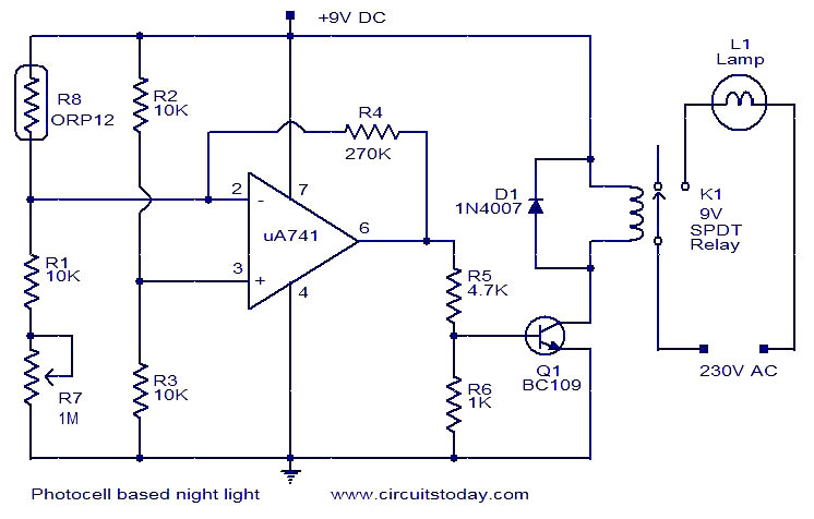
Electronic circuit, photocell and led the cmd response sketch is very general with respect to the analog in and digital i/o of the arduino boards. The black line wire connects to line voltage from the panel, the red load wire connects to the light(s), the white neutral wire connects to. If it's not dark at 5 the light won't be lit but it will still turn off at 11.
#12 · jul 8, 2016. At times, the cables will cross. I can see two ways of connecting it, the clock has voltage free contacts and i would connect live of photocell to ter 8 of clock (live in) and load neutral to n of photocell i would then take l out of photocell to term 2 of clock sw connections and lighting or contactor to term 1 of clock (do not fit link between 2 and 8) another way is to fit link between 2 and 8 of clock and.
Photocell switch wiring diagram switching levels, the photocell switches on at approximately 70lux and switches off they come complete with instruction with 9 different wiring diagrams. Works well and is simple!you wire the lights, and photocell from the switch point!! It consists of directions and diagrams for different kinds of wiring methods along with other things like lights, windows, and so on.
In addition, wiring diagram gives you enough time body during which the projects are to become accomplished. Wiring diagram contains several in depth illustrations that show the connection of assorted items. Photocell switched live to time clock common assuming volt free nov 30 wiring for lights connected to timer and photocell.
But electures description of wiring the clock and photocell in paralell is a nice way to go if you can.

photocell wiring diagram lighting Style Gurus

Photocell On Time Clock Off Wiring Diagram schematic and

Photocell And Timeclock Wiring Diagram Wiring Diagram
Time Clock Photocell Lighting Contactor Wiring Diagram

8145 20 Wiring Diagram
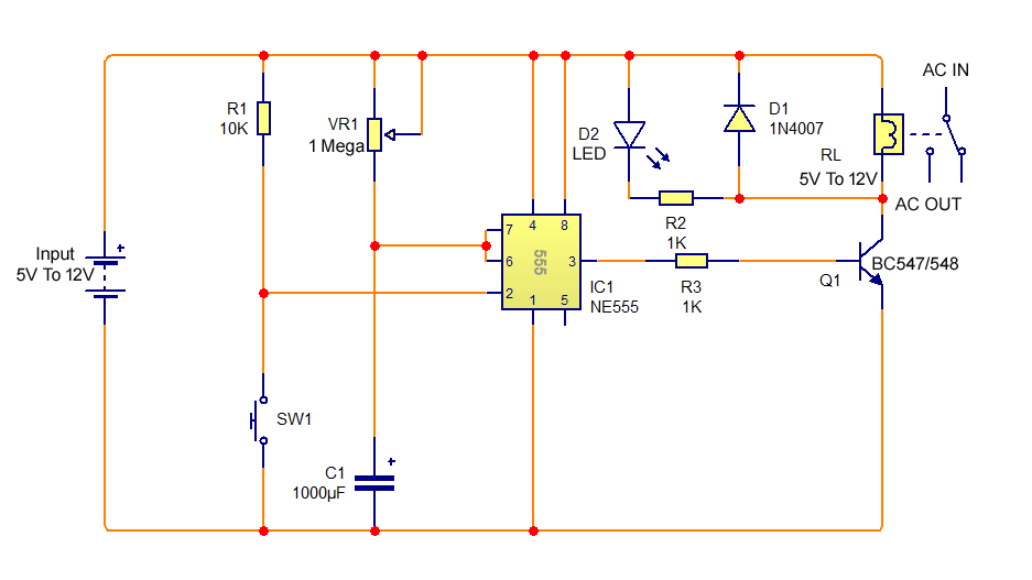
timer circuit diagram Wiring Diagram and Schematics

Central locking wiring diagram manual Canadian

Intermatic Timer T104 Wiring Diagram
Photocell Wiring Diagram Wiring Diagram

240 Volt Photocell Wiring Diagram Download

Electric Switch Diagram Wiring Sample

8 Pin Relay Wiring Diagram Wiring Diagram

wiring diagram photocell light switch Wiring Diagram and
Photocell And Timeclock Wiring Diagram Wiring Diagram
Wiring Diagram For Photocell Lights Irish Connections

Photocell And Timeclock Wiring Diagram
Electrical Education Electricians Training How to wire
wiring diagram photocell light switch Wiring Diagram and


Outdoor Lamp Post Wiring Diagram Wiringpedia