
We keep an extensive range of spare parts for swimming pool pumps, including pump baskets, mechanical seals cooling fans, capacitors, overloads and more. Usually, the wiring diagram is glued to one of the panels on the air conditioner.
31 Pool Pump Capacitor Wiring Diagram Wiring Diagram

Where one pump and one heater is used for either the pool or the spa.

Pool pump capacitor wiring diagram. A circuit is usually composed by many components. Please find below some popular exploded view diagrams for your convenience. Plumbing & water connections for pool/spa combinations use this diagram for a connected pool and spa, where the spa has a spill over type waterfall into the pool.
Not merely will it help you achieve your required outcomes more quickly, but also make the entire procedure simpler for everybody. Herm on capacitor goes to the start winding on the compressor, fan on capacitor goes to brown fan wire that goes to the fan, and. Split phase, capacitor start, permanent split capacitor and capacitor start/ capacitor run.
Many pool pump motors use a thermal overload protector that prevents the motor's windings from overheating. The first element is symbol that indicate electric component in the circuit. Look at the wiring diagram for your specific hvac equipment and find the capacitor where you’ll see its wires and their identities.
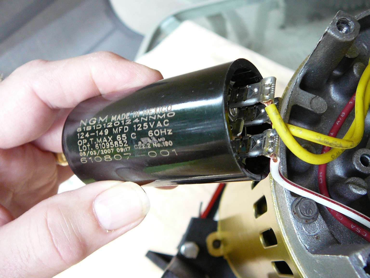
If you don't see what your after please contact us for details. Check the rating on the pool pump capacitor for replacement specifications. There are two things which are going to be present in any single phase motor wiring diagram with capacitor.
Unless you know how what you're doing, get someone to help you. If the water pump exceeds 1.5 h.p. Pool pump capacitor with wire quality.
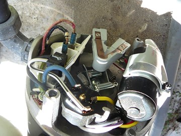
My pool pump started kicking off the switch in the control box, so i had the motor checked out for any problems and now i have it back and want to connect it. The split phase motor is used extensively in spa and jetted tubs, and above ground pools. Now i cannot recall how it was hooked up before.
On or near the nameplate is a. Century e plus pool pump duty. The first component is symbol that indicate electrical element in the circuit.
There are four common types of residential pool pump motors: You should see a wiring diagram glued to the inside of the air handler cabinet or to the inside of the blower compartment door. Wire a baldor 3 phase motor.
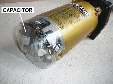
Start capacitors are usually located at the back of the motor. It includes guidelines and diagrams for different types of wiring methods as well as other products like lights, home windows, and so forth. Look for their mfd (or uf) and vac specifications.
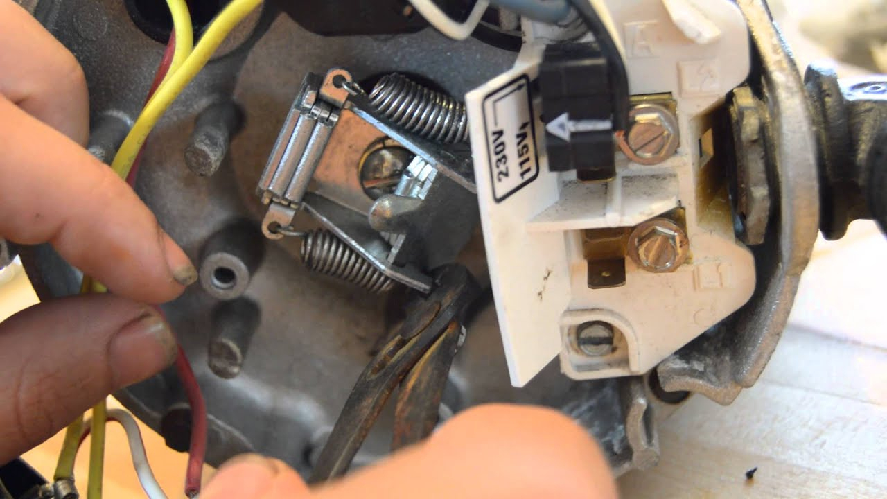
The motor has an auto reset overload switch and the starter capacitor. Pool pumps are wired to run on either v or v. The capacitor will have to be allowed 10 or more minutes to discharge before attempting this test again.
The motor runs one speed when i flip a switch. Try to replace the bad capacitor with an identical capacitor. There are just two things which are going to be present in any pentair pool pump wiring diagram.
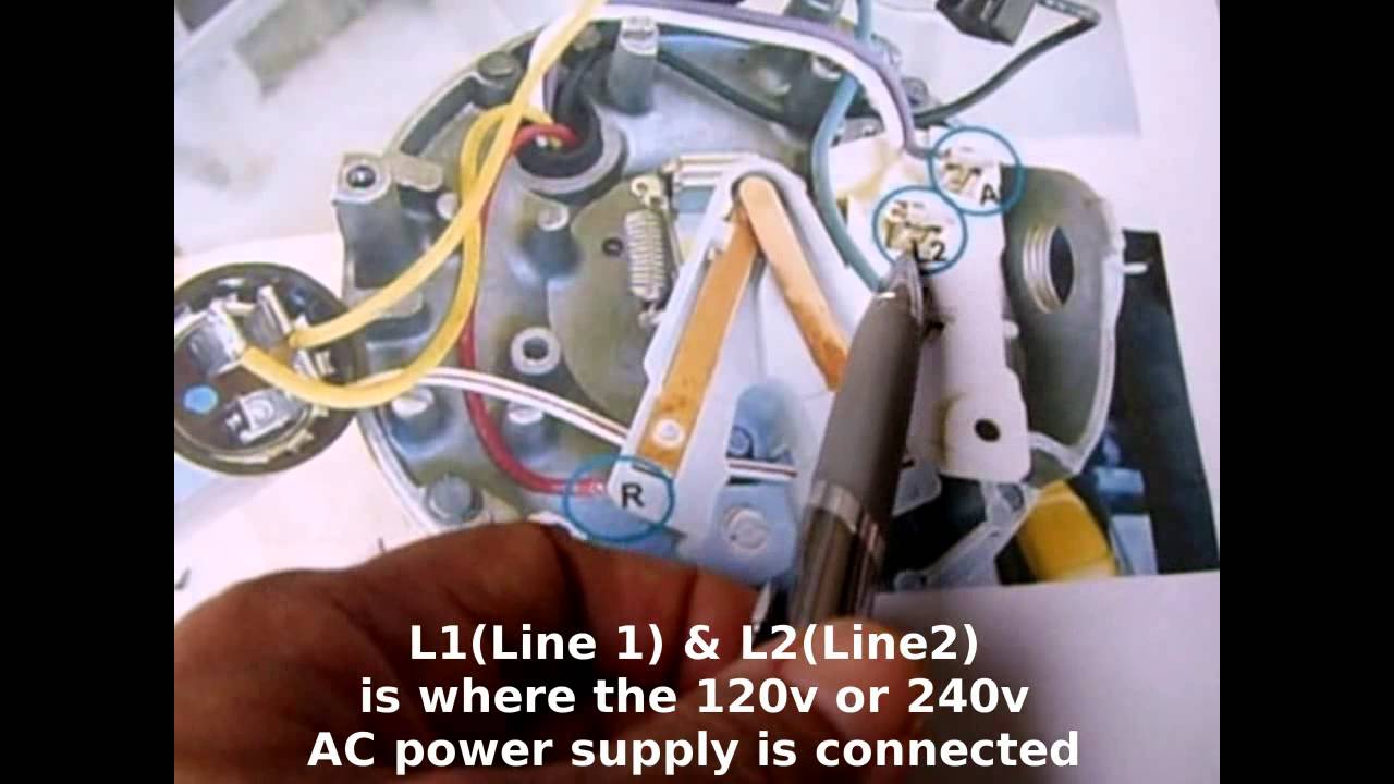
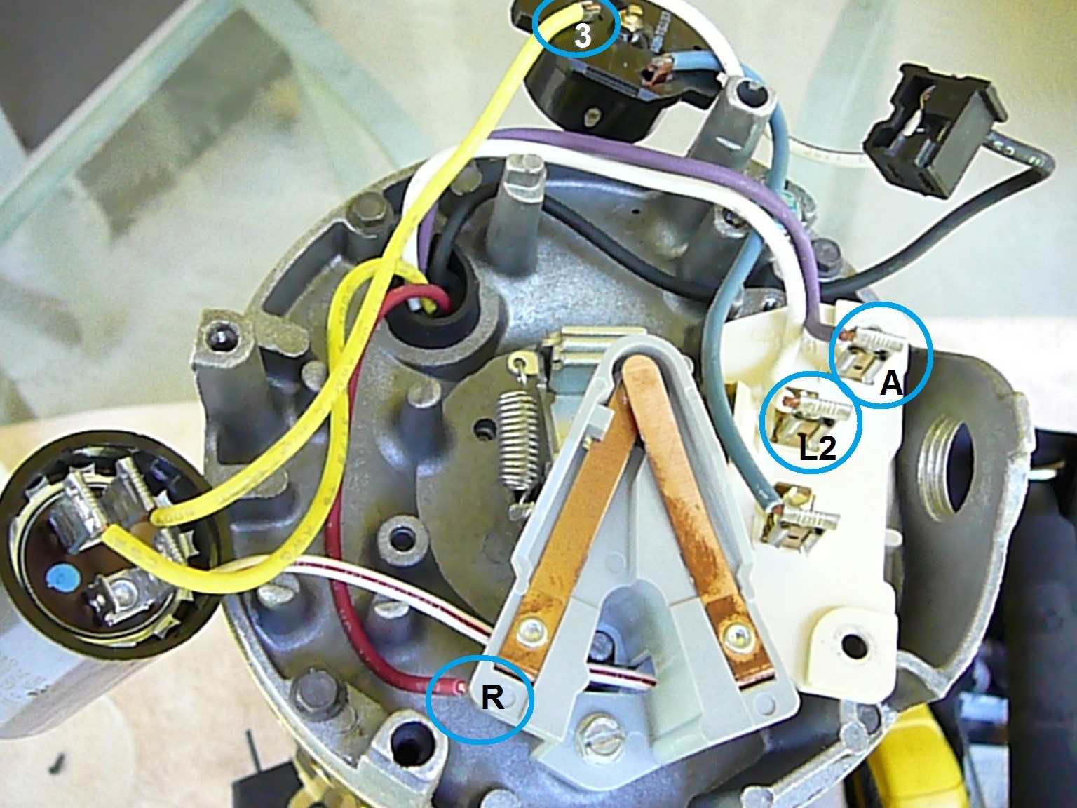
Push the wire terminal on the start capacitor relay's common wire, usually the black wire, to the common terminal on the load side of the unit's contactor. The pool timer acts like an automated switch. From a sticker on the motor, i can vaguely read:
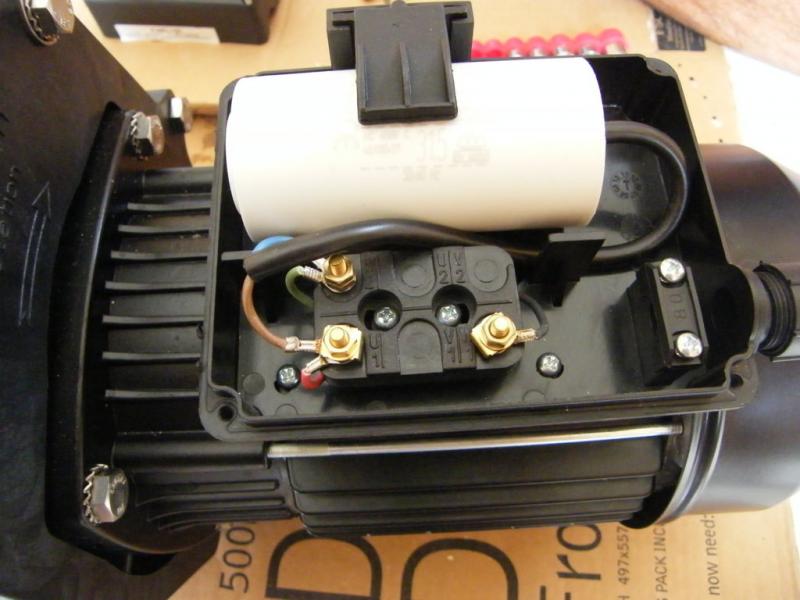
When i try to put it back on, i found there are three wires from the motor: With such an illustrative guide, you will have the ability to troubleshoot, stop, and full your tasks easily. Push the wire terminal on the start capacitor's second wire onto the run capacitor's common terminal, often labeled c, com. the wire connected to the motor's run terminal, marked as r on the motor's wiring chart, and the wire going to the hot terminal on the load side of the contactor also connects to this run capacitor terminal.
Hope you can read it. Then install either of the optional bypasses as shown on page 5. I took off the capacitor and after some time, ordered a new replacement.
Wiring diagram includes numerous in depth illustrations that show the link of varied products. Replacing the capacitor in my davey pump and although there is a wiring diagram on the pump, there are two wires (blue and light blue) but the digram just says blue for both ? The other thing that you will get a circuit diagram would be traces.
Capacitor also doesnt have a pinout legend that i can see. Rule of thumb on wiring the capacitor is: Round dual capacitors on the top should be marked:
It includes directions and diagrams for different types of wiring methods and other products like lights, windows, etc. A circuit is usually composed by many components. They will vary by manufacturer.
Wiring diagram includes numerous comprehensive illustrations that show the relationship of assorted items. For example a house builder would want to look at the location of electrical outlets and light fixtures by using a wiring diagram to stop costly mistakes and building code violations. Maintain, troubleshoot and service a.o.
Problem is, i lost the diagram i drew when i disconnected the wires and i just want to make sure i have it all correct before switching it on.

Pool Pump Capacitor Wiring Diagram For Pmb40
Anatomy of a Pool Pump

Wiring Diagram On Extremepowerus Pump

32 How To Wire A Pool Pump Motor Diagram Wire Diagram
33 Pool Pump Capacitor Wiring Diagram Wire Diagram

How To Wire A Pool Pump Capacitor

Hvac Motor Start Capacitor
Hayward Super Pump Wiring Diagram Cadician's Blog
33 Pool Pump Capacitor Wiring Diagram Wire Diagram
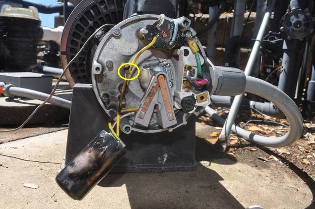
How the Common Capacitor Start Pool Motor Works
Pool Pump Capacitor Wiring Diagram For Pmb40

Hayward Super Pump Wiring Diagram Wiring Diagram
Pool Pump Capacitor Wiring Diagram Hanenhuusholli
How To Replace a Pool Pump Capacitor
Hayward Super Pump 115v Wiring Diagram

12+ Baldor Electric Motor Capacitor Wiring Diagram

Sta Rite Pump Wiring Diagram Wiring Diagram And

Hayward Pool Pump Capacitor Wiring Diagram Electronic
Pool Pump Capacitor Wiring Diagram For Pmb40