
Free press series on homelessness. Power trim tilt motor and wire harness kit p n 584107 crowley marine.
Mercruiser Starter Solenoid Wiring Diagram inspire ideas
Quicksilver 3000 series panel mount mercruiser remote control tilt/trim.

Quicksilver trim switch wiring diagram. 0078 boat trim wiring diagram wiring resources. To remove the handle shift the control backwards to about 14 to 12 position this will enable you to popout the push button for nuetral. Do the math on 4 of those puppies and before i spend over $ commander classic panel remote control.
Behind that button is a bolt remove it and the handle will come off. (32)a boat's trim switch activates the trim/tilt system that raises and lowers your outboard motor. Blk = black quicksilver the.
Quicksilver 3000 series trim control wiring diagram keywords: Line up the notch in the bezel with the rectangular protrusion in the bushing. Commander 3000classic panel mountremote control 74428 11table of contents pagecommander 3000 classic remote control maintenance and replacement parts 111disassembly 112cleaning and inspection 115assembly 11511 commander110 3000 commander classic 3000 panel classic mount panel remote mount control.
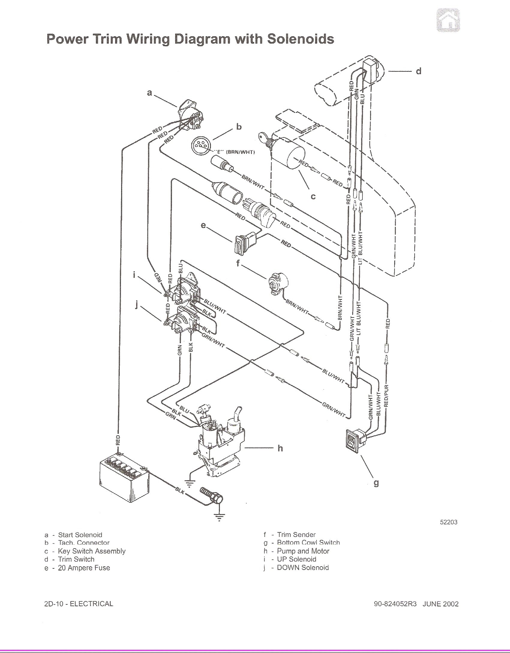
When the pump operates in the downward mode. 4e safety switch in engine. Power trim wiring diagram with solenoids 2d commander classic panel remote apply quicksilver liquid neoprene to connections and.
Route new trim limit switch. Quicksilver trim switch wiring diagram. Quicksilver disassembly/ trim switch hi this is how you take off the handle to get to the switch and wires.
Locate a place on the dashboard to install the toggle switch. To remove the handle shift the control backwards to about 1/4 to 1/2 position this will enable you to popout the push button for nuetral. Read book quicksilver 3000 series trim control wiring diagram 27799 listings | kijiji in lethbridge.
A wiring diagram is a streamlined standard pictorial representation of an electrical circuit. Blk/yel is the kill switch. Red, black, light brown, gray, purple, black w/yellow strip, yellow w/ red stripe, yellow w/ black stripe.i'm assuming red and black are hot and ground for ignition.then the others will control the netrual safety, ignition on, choke.and that leaves some more wires.whatever help or direction would be great.as said before i'm trying to get an old engine.
Your safety lanyard in the throttle grounds this wire inside the throttle if the lanyard is pulled out,. The trim switch on my throttle 3e88dbd8be friends,.jan 11, 2011 뜀 address unknown: Mercury trim gauge mercruiser outboard quicksilver 79 895292a01 gauges wiring bottom line isle of man.
Try teleflex marine’s ch7800 series dual top mount control for maximum pilot control. When the pump operates in the downward mode. However, these wires are quite a light gauge compared with the wiring in the power trim pumps and looms, so i am concerned about connecting them.
Or handle, a pump motor and a trim limit switch,. Trim and tilt blue wire is up position green wire is down position about press copyright contact us creators advertise developers terms privacy policy &. Neil, yel/red is the crank wire, goes to the starter's solinoid.
Mercruiser trim/tilt wiring for the position sender, the diagram shows one side to ground, and the other side to a brown/white wire, that goes to the connector, and on up to the trim gauge. Also, disconnect trim sender wires at the engine harness. Diagram of the “down” circuit.
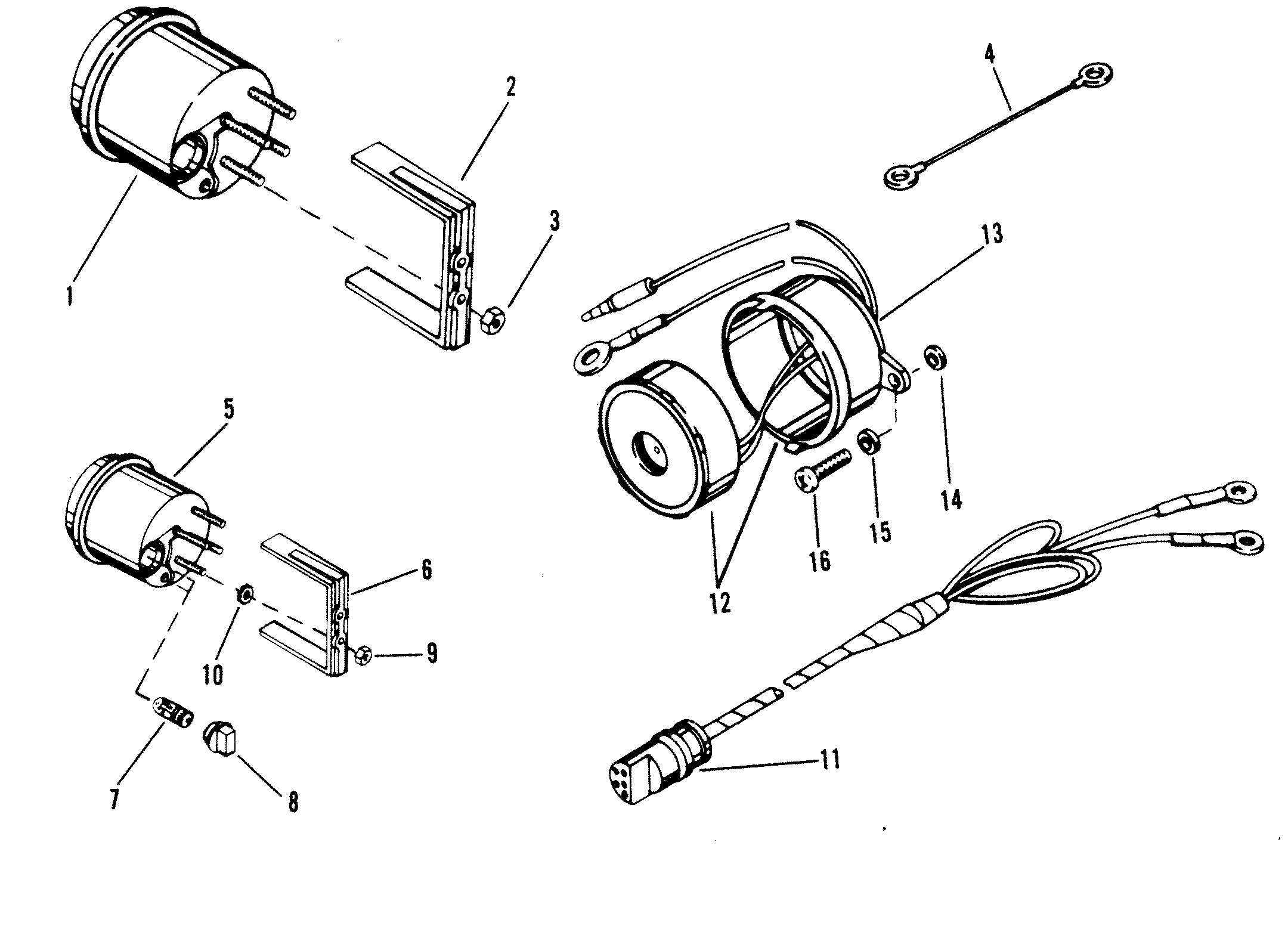
Up / down and common. Tachometer wiring diagram tachometer dial on back side of case must be set to position number 4. E tec rigging trim gauge moderated discussion areas.
Quicksilver 3000 series trim control wiring diagram author: How to wire power trim silinoid and 2 switches. For your model place your drive in the bravo 1 position as the trim does not move that far in the stock bravo 3 position will cruising and some trim changes barely register on the gauge.
Diagram of the “down” circuit. 1 mercruiser tilt trim wiring diagram. Pull back on bell housing and rotate it 90 degrees to gain access to the trim wire retainer bolt.
This remote control features a finger tip neutral lock release, throttle only option, power trim switch, and a lanyard stop from the quicksilver's panel control, you can adjust your boat's trim, or angle in the water, to raise your bow to the appropriate level in various weather conditions and at different speeds. Or handle, a pump motor and a trim limit switch,. I have identified the 5 wires relating to port up / down, stbd.
Connected the trim sender wires from the lower unit to the brown/white and black wires which match the original wiring connections. Viewing a thread 2 wire motor trim wiring diagram. Tilt and trim switch wiring diagram best trim and hydraulics need.
Each part should be placed and connected with different parts in specific way. Wiring a toggle switch to the power tilt and trim is a fairly straightforward job. Trim sender smartcraft offsonly com.
I have a quicksilver dual throttle control, which has the two trim switches built into one of the throttle levers. Quicksilver, 3000, series, trim, control, wiring, diagram created date: Wiring diagram a use this wiring diagram when using a separate light switch for instrument lighting.
On quicksilver 3000 classic wiring diagram. Disconnect trim limit switch wires at the power trim pump. Install the bushing into the commander 3000 classic bezel.
Quicksilver 3000 series panel mount outboard remote control tilt/trim.

Volvo Penta Ignition Switch Wiring Diagram

Mercruiser Starter Solenoid Wiring Diagram inspire ideas

Mercruiser Trim Wiring Diagram

Mercruiser Starter Solenoid Wiring Diagram inspire ideas

Mercruiser Starter Solenoid Wiring Diagram inspire ideas

Volvo Penta Ignition Switch Wiring Diagram

Volvo Penta Ignition Switch Wiring Diagram
Power trim is not working, I have an auditable click at


Omc Control Box Wiring Diagram The Wiring

Mercruiser Starter Solenoid Wiring Diagram inspire ideas
Quicksilver Trim Switch Wiring Diagram

Mercruiser Starter Solenoid Wiring Diagram inspire ideas

Mercruiser Trim Wiring Diagram

Mercruiser Trim Wiring Diagram

Mercruiser Trim Wiring Diagram

Quicksilver Trim Switch Wiring Diagram

Mercruiser Slave Solenoid Wiring Diagram All About

Omc Control Box Wiring Diagram The Wiring
Quicksilver Trim Switch Wiring Diagram