
Wiring diagram arrives with several easy to adhere to wiring diagram instructions. At times, the wires will cross.
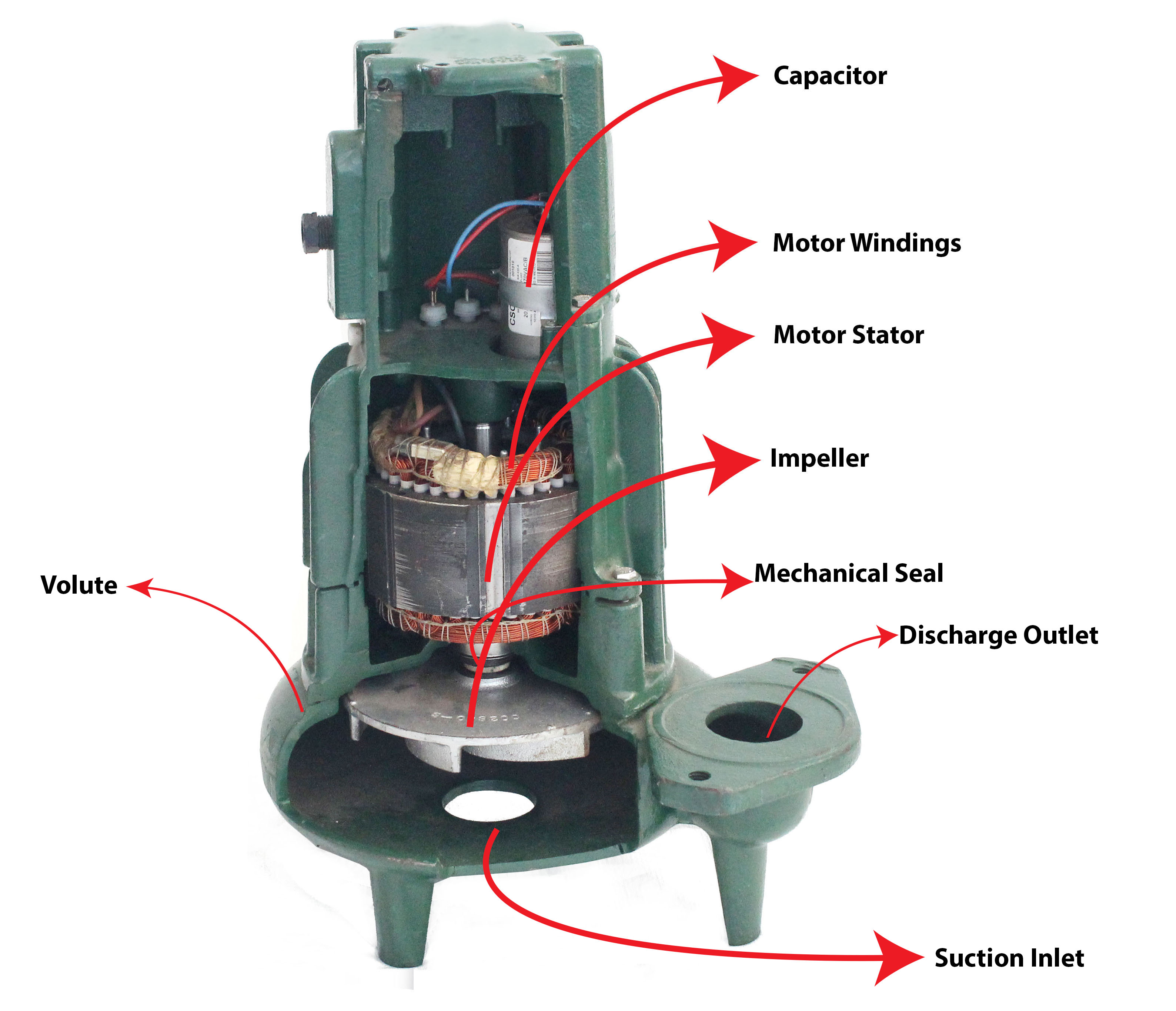
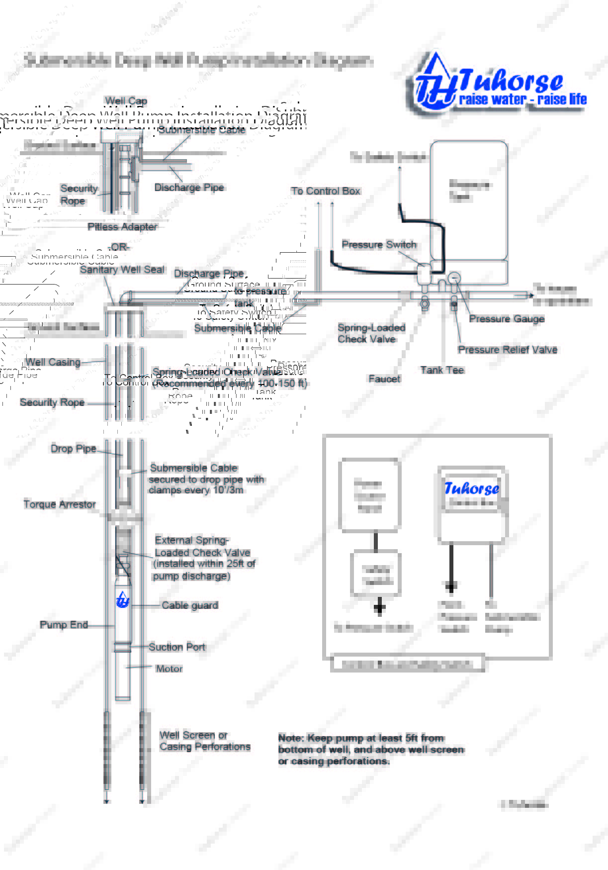
Cutaway diagram of a submersible sewage pump.
Same day shipping 4 locations.

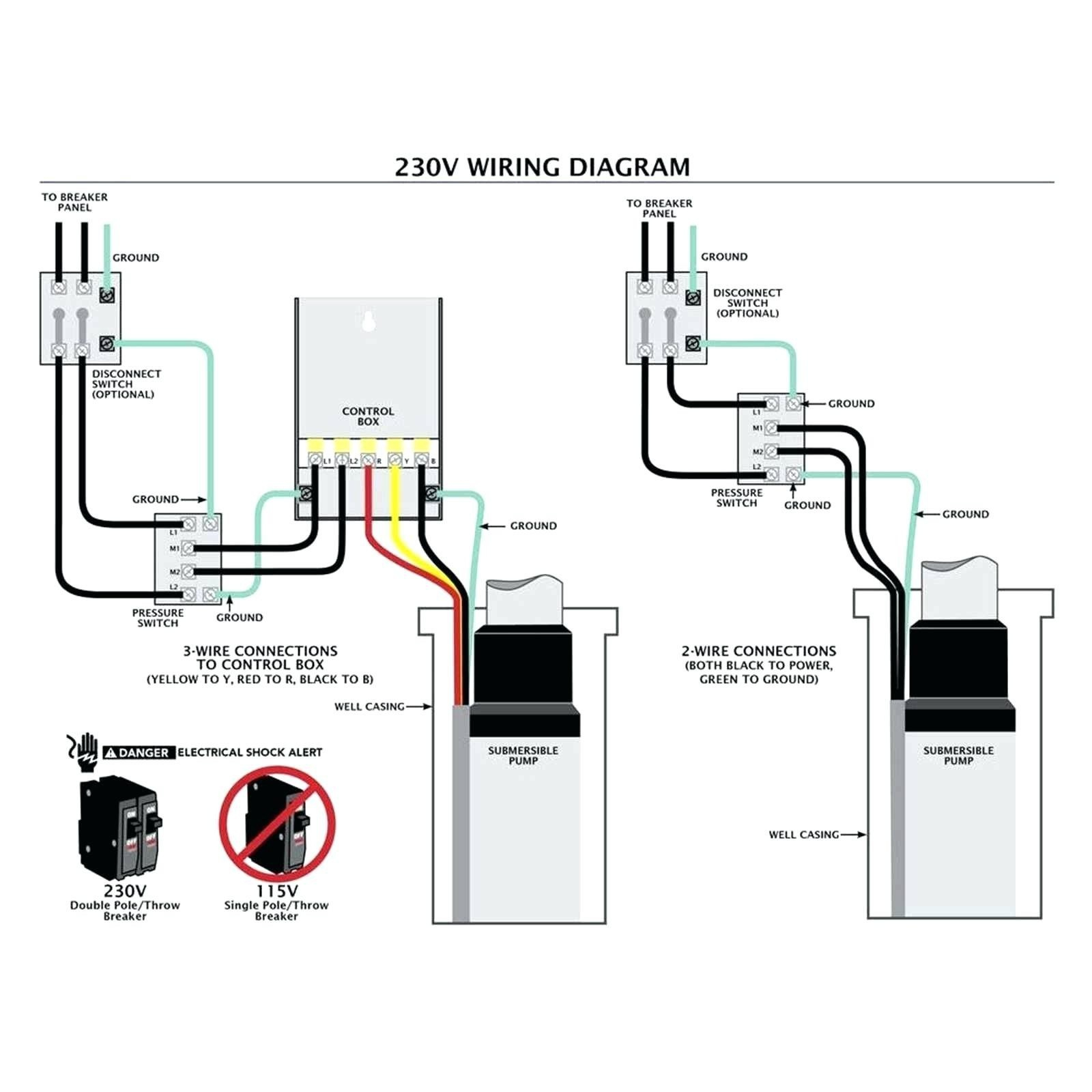
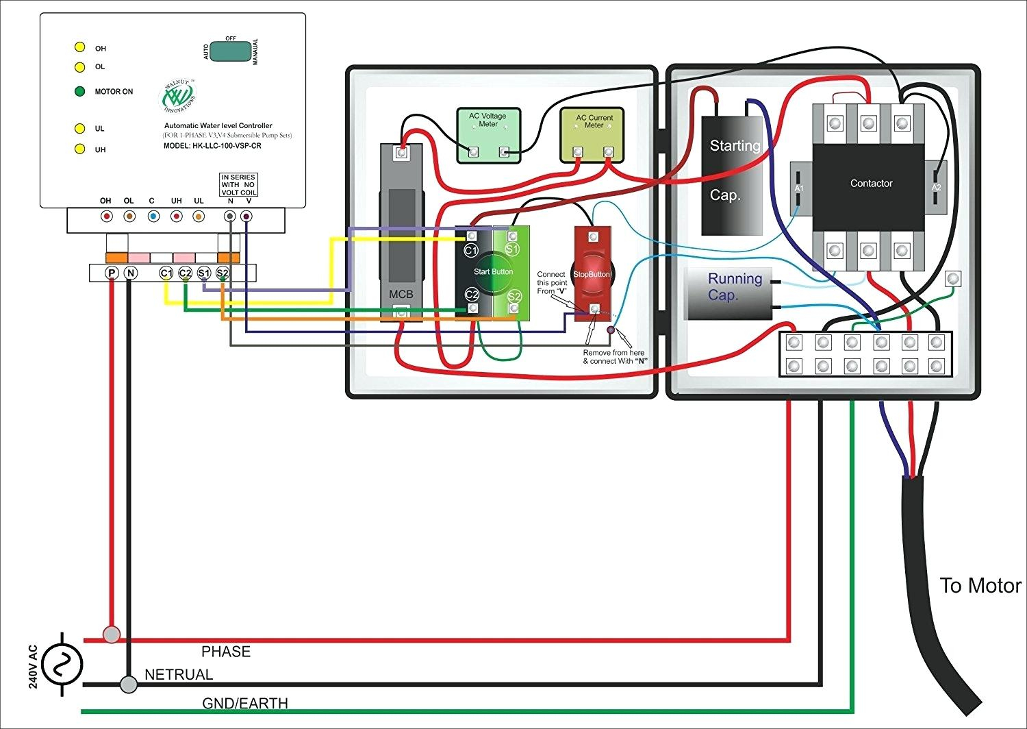
Submersible pump wiring diagram. The wiring connection of the submersible pump control box is very simple. The above diagram is a complete method of single phase motor wiring with circuit breaker and contactor. Line voltage must match pump voltage.
Grundfos pump motor wiring diagrams. Assortment of submersible pump control box wiring diagram. All 3 wire (plus ground) pumps require a control box that matches the pump hp and voltage.
Learning how to read well pump wiring diagrams is necessary to install a well pump properly. Injunction of 2 wires is generally indicated by black dot to the intersection of 2 lines. As stated previous, the traces at a 2 wire submersible well pump wiring diagram represents wires.
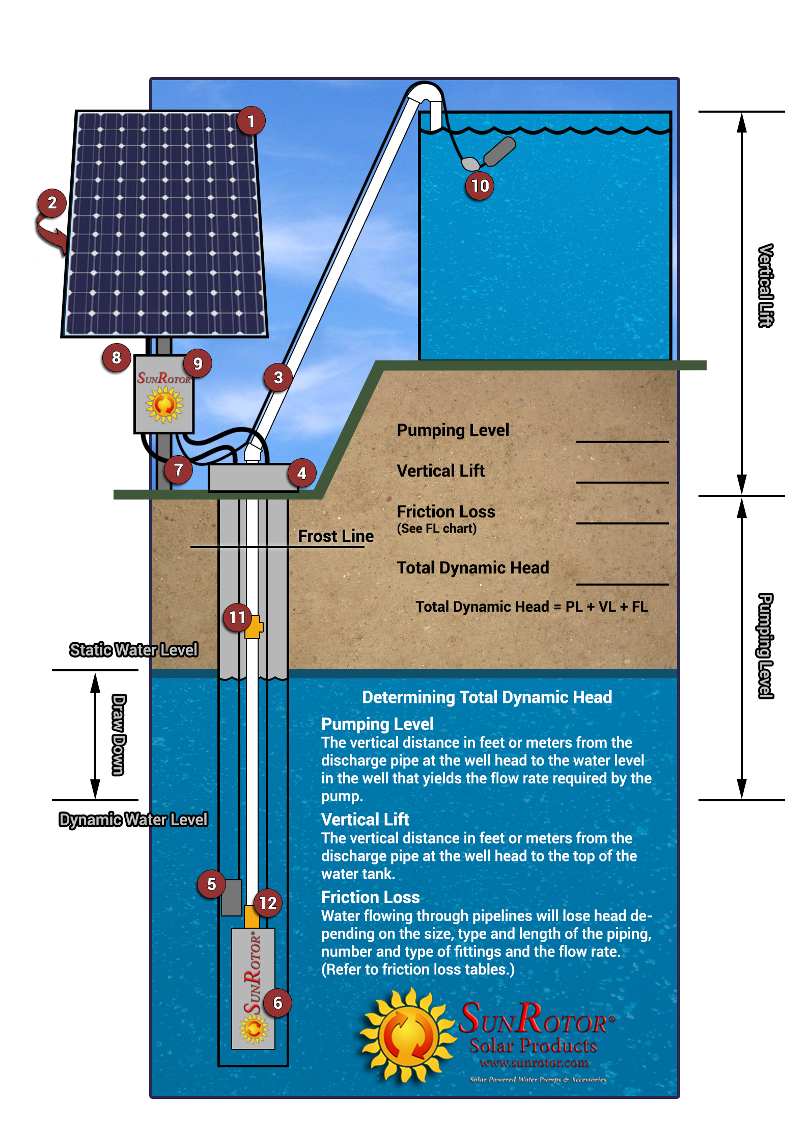
Typical submersible pump installation 1. The air level in the tank should be 2 lbs. However, the diagram is a simplified version of this structure.
Normal delivery may resume if water pump is started and stopped at one minute intervals. It really is supposed to aid each of the typical consumer in developing a proper system. Understanding well pump wiring diagrams.
These guidelines will likely be easy to understand and implement. The heat shrink tube is then slid over one end, the wires insert into the stakon connector. Pump starts and stops 1.
A guide of 3 phase submersible pump wiring diagram with direct online starter using contactor mccb overload relay and push button switches. Remove 3 8 9 5 mm of the insulation from the ends of the motor leads and power supply wires. Single phase submersible pump wiring diagram wiring diagram is a simplified pleasing pictorial representation of an electrical circuit.
Submersible well pump wiring diagrams. 18 franklin electric wiring diagram submersible well pump jet pump well pump. It shows the elements of the circuit as simplified forms and also the power as well as signal links between the devices.
The circuit to the well pump is a dedicated circuit. A wiring diagram is a simplified standard pictorial depiction of an electrical circuit. Wiring diagrams for all at.
Here is the complete guide step by step. For proper installation in a submersible pump application, you must strip 1/4 of insulation from the wire. Control panel, must comply with the circuit diagram of the control panel as well as the motor connection diagrams, and must be carried out by a qualified person.
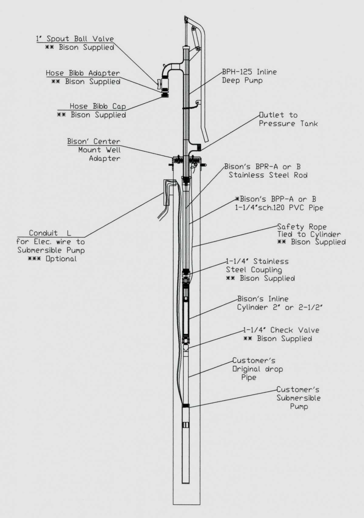
This really is helpful for each the people and for experts that are searching to learn more on how to established up a operating surroundings. Deep submersible well pumps will be either 2 wire or 3 wire well pumps and 3 wire well pumps will need a separately installed control box. Diagram two wire submersible well.
Submersible pump control box wiring single phase earth bondhon submersible pump submersible schematic drawing. Thanks for visiting our website to search submersible pump control box. However, it does not mean link between the cables.
It has significantly higher drawdown than a standard pressure tank and eliminates water logging problems. Of air with the tank dry. Wiring diagrams 22 23 typical wiring a diagrams 3 1 2 5 36 97 3 4 31 42 1 l1 t1 t2 t3 2 l2 3 start hand/off/auto to pump motor ground level control ground pressure switch lower upper electrode to fused disconnect or circuit breaker 3ø furnas pumping panel line load line load 3 phase starter input power (as required by.
Submersible pumps are usually installed in wells which are at least 90. Franklin electric submersible pump wiring diagram wiring diagram is a simplified all right pictorial representation of an electrical. Older pumps had no ground wire.
The diagram provides visual representation of a electrical structure. The heat shrink is then crimped to attach the stakon to the wire. Wiring diagram for 220 volt submersible pump bookingritzcarlton info in 2021 submersible well pump submersible pump submersible 44 luxury single phase submersible pump starter wiring diagram submersible well pump jet pump well pump
2wire submersible well pump wiring diagram pics pictures variety of which publicized here was accurately picked and also authored by admin right. 3 phase submersible pump wiring diagram with dol stater electrical online 4u electrical circuit diagram electrical diagram motor. 3 phase submersible pump wiring diagram.
Check for correct wire size. A wiring diagram is a streamlined standard pictorial depiction of an electric circuit. Single phase submersible pump starter wiring diagram building wiring representations reveal the approximate locations as well as affiliations of receptacles lighting as well as irreversible electric solutions in a building.
The purpose is the very same. Submersible well pump wiring diagrams. 2 wire well pump wiring diagram.
It makes the procedure for assembling circuit easier.

Submersible well pump installation & Troubleshooting
3 Wire Submersible Pump Wiring Diagram Diagram Stream


Beauchamp Water Treatment Blogspot Submersible Well Diagrams
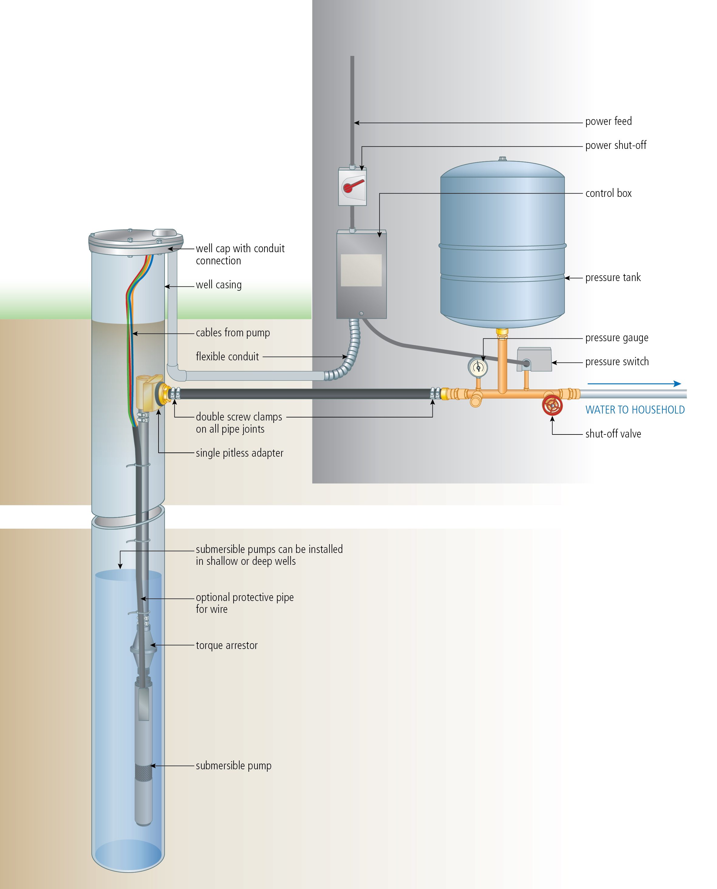
INSTALL A SUBMERSIBLE PUMP 6 Lessons for doing it right

Wiring Of Flotec Well Pump Diagram Submersible Well Pump

Typical Electrical Submersible Pump system and main
3 Wire Well Pump Data Wiring Diagram Schematic 3 Wire

Submersible Well Pump Wiring Diagram Gallery
Submersible Motor Control Box Wiring Single Phase water

2 Wire Submersible Well Pump Wiring Diagram Gallery
3 Wire Submersible Pump Wiring Diagram Wiring Diagram

Water Pump Wiring Troubleshooting & Repair
3 Wire Submersible Pump Wiring Diagram Wiring Diagram
Pump Installation
Single Phase Submersible Pump Panel Wiring Diagram


Submersible Pump Control Box Wiring Diagram For 3 Wire
Submersible Pump Installation Diagram Hanenhuusholli

Stainless steel submersible pump installation diagram.jpg
2 Wire Submersible Well Pump Wiring Diagram Cadician's Blog