
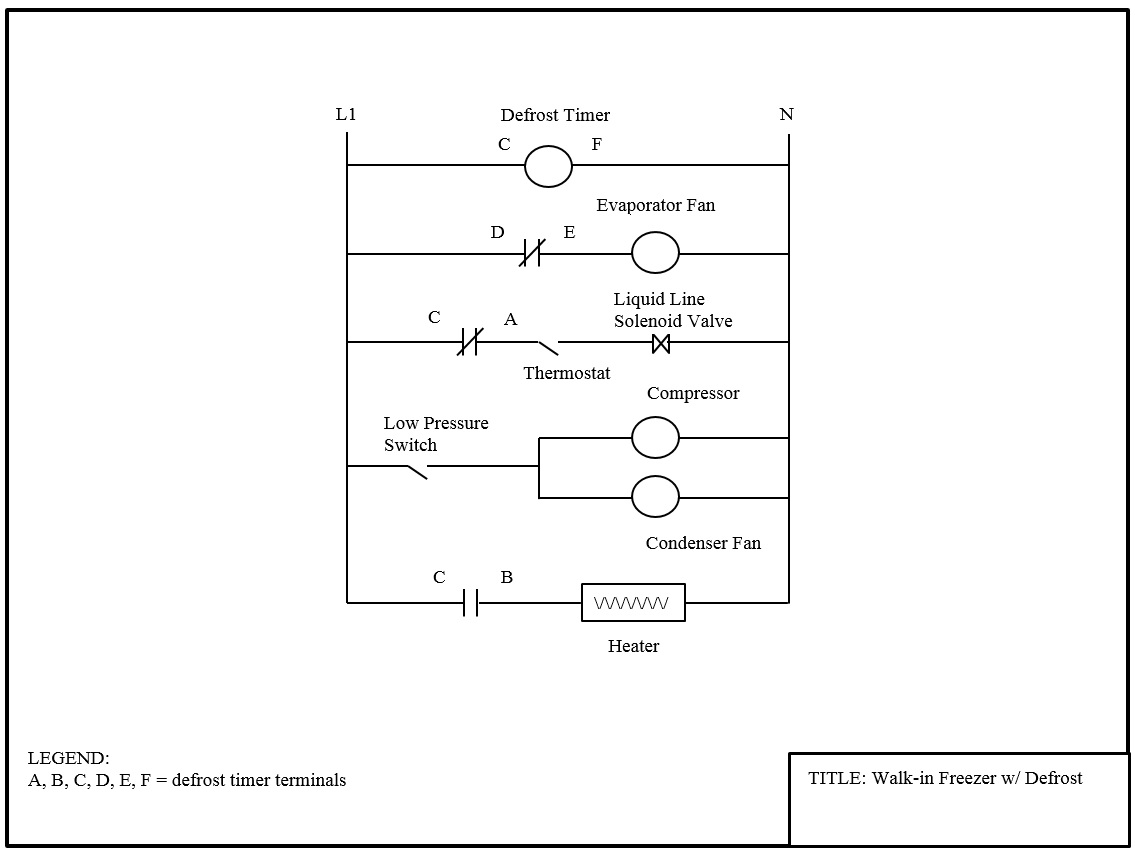
At the condenser contactor, the defrost timer is wired in series with the high pressure switch and the low pressure control. • if so, the red light should illuminate on timer.
Bohn Freezer Evaporator Wiring Diagram 26
There is no separate air defrost timer.

Walk in cooler defrost timer wiring diagram. If playback doesn't begin shortly, try restarting your device. As shown in the wiring diagram. The defrost timer shall be housed in a ul type 3r indoor/ outdoor plastic enclosure.
O n is common leg and timer switches the other single phase leg (terminal 1) between terminals 4 and 3. The defrost timer shall also incorporate a short cycle delay adjustable from 0 sec. Jul 01 i am trying to install a defrost timer on a commercial freezer.
O manually advance timer into defrost. The condensor has a 125 lrc (locked rotor curent) 208v. A small split system for a walk in cooler with 3 electrical devices;
Max to prevent rapid compressor cycling. • electric defrost timer (freezers) additional details on page 21. Wiring diagram for walk in freezer.
Walk in freezer defrost timer wiring diagram. Usually makes for shorter wire runs. It reveals the parts of the circuit as simplified forms as well as the power and also signal connections between the tools.
Walk in freezer defrost timer wiring diagram. The dtav40 defrost control automatically selects the appropriate voltage between wiring diagrams. If it's wired in series with the heaters from 3 to n, it's correct.
• set the defrost control time and verify the defrost initiation settings. Here are a number of highest rated walk in freezer wiring pictures upon internet. The grässlin dtav40 series auto voltage defrost timer is applicable to air defrost (compressor.
• make electrical connections as directed by the wiring diagram. The easiest way to correct this problem is to relocate the defrost timer into the evaporator and break power to the liquid line solenoid valve during defrost. Its submitted by direction in the best field.
For electric heat, hot gas or compressor shutdown defrost. We identified it from reliable source. • if not, inspect timer and termination switch.
Oct 24, · heatcraft only has typical wiring diagrams for their unit coolers available online. A compressor, this type of wiring diagram has branch runs all shown as parallel circuits going from (defrost systems are only a standard item with freezers) if a refrigeration.walk in freezer wiring schematics ~ welcome to our site, this is images about walk in freezer wiring. The most common form of defrosting a freezer's unit cooler is done by control for the evaporator is wired to terminal “x” on the defrost timer.
The diagram below shows how it was initially connected and then how we rectified the situation. We take this nice of walk in freezer wiring graphic could possibly be the most trending subject afterward we allocation it in google help or facebook. Getting from point a to aim b.
208/230 should be present between terminals n and 3. A wiring diagram is a simplified standard pictorial depiction of an electric circuit. • air defrost timer (coolers) is incorporated into the air defrost thermostat.
This is pretty much normal for a defrost timer. 26+ walk in freezer defrost timer wiring diagram pictures.up to 5 years warranty. Did the timer go into defrost?
At the condenser contactor, the defrost timer is wired in series with the high pressure switch and the low me neither, even. 3 phase walk in freezer wiring diagram. We decide to explore this walk in freezer defrost timer wiring diagram pic on this page simply because based on info from google engine, it is one of the top searches keyword on google.
Walk in cooler wiring diagram. I just use the timer to interrupt the solenoid circuit. Intermatic/grässlin's defrost controls just got even better!
That two wire t'stat is the heater limit (hl). The writers of 3 phase walk in freezer wiring diagram have made all reasonable attempts to offer latest and precise information and facts for the readers of this publication. Walk in freezer wiring diagram you will want a comprehensive professional and easy to understand wiring diagram.
October 19, 2021 on typical wiring diagram walk in cooler. The proper diagram should be #2 on p for a single evaporator with electric defrost. The most common form of defrosting a freezer s unit cooler is done by control for the evaporator is wired to terminal x on the defrost timer.
29 Walk In Freezer Defrost Timer Wiring Diagram Wiring


29 Walk In Freezer Defrost Timer Wiring Diagram Wiring

Walk In Freezer Defrost Timer Wiring Diagram
35 Refrigerator Defrost Timer Wiring Diagram Wiring

Walkin Freezer Defrost Timer Wiring Diagram
Walk In Freezer Defrost Timer Wiring Diagram Atkinsjewelry


Freezer Defrost Timer Wiring Diagram 2 Circuit diagram

Wiring Diagram For Walk In Freezer Wiring Diagram Database
Find Out Here norlake Freezer Wiring Diagram Download

Collection Of Walk In Freezer Wiring Diagram Sample

Walk In Freezer Defrost Timer Wiring Diagram Wiring

WalkIn Freezer Defrost Timer Wiring Diagram Collection

814100m Defrost Timer Wiring Diagram
Walk In Freezer Defrost Timer Wiring Diagram

Walk In Freezer Defrost Timer Wiring Diagram Wiring
Walk In Freezer Defrost Timer Wiring Diagram Atkinsjewelry

Walk In Freezer Defrost Timer Wiring Diagram


Collection Of Paragon Defrost Timer 8145 20 Wiring Diagram
Freezer Defrost Timer Wiring Diagram