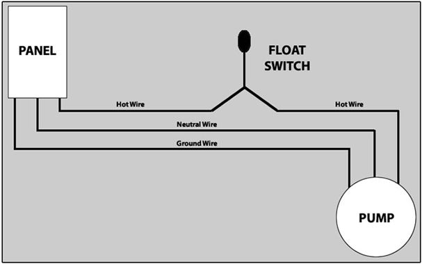
3 wire float switch wiring diagram. If the tank gets near empty the float switch will operate and open circuit the active connection to the pump, therefore stopping the pump.
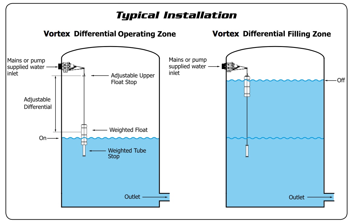
Vortex Differential Valve Irrigation Direct
The wiring or most of the switch for that matter is never in the mash water.

Water tank float switch wiring diagram. It can either be fixed to a bracket on top of the water tank, or along the side/pipe running down inside the tank. There is a mounting bracket available for the kari float switch that uses a snug wedge to fix the cable into place. If not, the arrangement will not work as it ought to be.
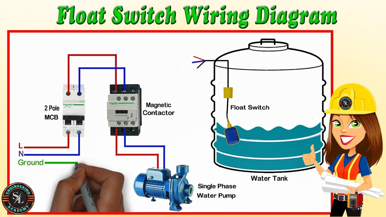
Ad find deals on products in camping hiking on amazon. Here are a number of highest rated water tank float switch pictures on internet. Float switch wiring diagram for water pump float switch connection single phase water pumpwhat is float switch?float switch is a type of level.
Float switch controlled water level controller circuit homemade projects. 14.01.2019 · the float switch moves with the water level in the tank and this determines when the pump turns on please note: Referring to the diagram shown below, the various.
This circuit can be used to fill a water tank automatically. Float switch wiring diagram for water pump. Let s start with the most basic float switch.
For example water level controls is a float. In this article, we are going to see float switch connection diagram and wiring. Septic tank float switch wiring diagram shahsramblings septic tank float switch wiring diagram the diagram provides visual representation of a electric structure.
Float switch wiring automatic manual single phase water pump controller water pump youtube electrical circuit diagram water level switch water pumps. It shows the components of the circuit as simplified shapes and the knack and signal associates with the devices. The 'float' part of the switch simply goes up and down.
It shows what sort of electrical wires are interconnected and may also show where fixtures and components may be connected to the system. As the liquid level goes up or down, it moves vertically with the liquid level. We identified it from reliable source.
The electrical wire needs to be fixed in a position that isn’t going to change the depth of the float switch, as seen in figure 2. Float switch installation requires you to mount the device with some way of fixing the cable above the tank or well. 2 built in bilge running indicator.
We endure this kind of water tank float switch graphic could possibly be the most trending topic behind we share it in google help or facebook. Float switches of the 21st century have come much. It shows the components of the circuit as simplified shapes and the capability and signal connections amongst the devices.
Older float switches work by opening and closing circuits dry contacts as water levels rise and fall. Wiring diagram of 2 float switch for two tanks wiring diagram of 3 motors diagram guitar fender also well and septic systems diagnostics. Jan 24 18 02 09 pm.
A float switch is a mechanical switch that floats on top of a liquid surface. A float switch consists of the floating switch and the electrical wire. Below is a diagram of what is described in the paragraph above.septic solutions® carries a large selection of septic tank alarms, control panels, and float switches.
A wiring diagram is a simplified standard photographic representation of an electric circuit. Water level control’s new float switches work by using probes (instead of floats) to detect or (sense) water levels in a storage tank (water, oil, gas, etc). Let’s start with the most basic float switch:
Therefore in normal operation the float switch relay contacts are 'made' and 220 v is applied to the pump motor. Its submitted by management in the best field. Float switch is basically is the combination of no and nc circuit that changes its contacts depends upon the alignment at which it is placed.
They certainly dont apply in all scenarios especially when additional control equipment is needed to handle large motors. Each part ought to be set and connected with different parts in particular manner. The information below refers to v pumps and wiring.
The pump from the water tank supplies water to the house and several taps in the yard. For example, water level controls is a float switch manufacturer that is revolutionizing the way float switches are used for water level sensing. This bracket can be attached to a wall or a rail using a simple bolt or screw.
Typical float switches are normally resting in the closed position meaning the circuit is incomplete and no electricity is passing through the wires yet. Shurflo 9300 wiring diagram for pumping into a pressurized tank submersible well pump well pump water pumps. Float switch connection single phase water pumpwhat is float switch?float switch is a type of level sensor a device used to detect the level of liquid within.
As the liquid level goes up or down, it moves vertically with the liquid level. This makes the process of building circuit easier. The float switch moves with the water level in the tank and this determines when the pump turns on please note:
45+ septic tank float switch wiring diagram. Float switch installation wiring how to wire a tameson com diagram skyhooks and cable with 3 mtrs install an automatic pump controller bilge maretron equipment 9 19 eur 2m 250v 16a continuous level sensor terry love 110 220 fuel tank selector controlled water single phase. Wiring diagram of 2 float switch for two tanks wiring diagram of 3 motors diagram guitar fender also well and septic systems diagnostics.
Single phase submersible pump starter wiring diagram on water control panel inside to. If not, the arrangement will not work.
Float Switch Wiring Diagram for Water Pump/ How to Make

35 Float Switch Wiring Diagram Wiring Diagram Database

How to control level of a tank with float switch

Water Tank Float Switch Wiring Diagram

Tank Float Switch Wiring Diagram Dual Complete Wiring
How To Hard Wire A Float Switch To A Submersible Pump

Tank Float Switch Wiring Diagram Dual Complete Wiring
Everything You Need to Know about Float Switch

Water Tank Float Switch Wiring Diagram

DC / AC Float Switch, Water Level and Bilge Pump Control

Wiring Diagram For Float Switches Wiring Diagram Dash

Wiring Diagram For Water Pump Wiring Diagrams

float switch wiring diagram for water pump « Palm Oil Industry

28 Septic Tank Float Switch Wiring Diagram Wiring

{Wiring Diagram} Water Tank Float Switch Wiring

Float switch Wiring singlephase water Pump water Pump
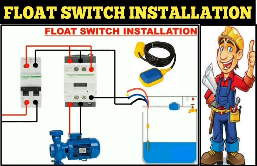
Float Switch Installation For Water Tank Float Switch

Safe & Simple Water tank Level Float Switch Wiring Diagram

230v Float Switch Wiring Diagram