
Line 1 goes to another junction box and then connects to the office ceiling fan somehow. 3 way switch wiring diagram.
wiring diagrams for lights with fans and one switch Read
Switching the light and fan from the same switch (single switch) this is a slight adaptation of the above method.

Wiring diagram for 2 fans on one switch. Fan wiring diagrams for two switches ceiling fan wiring diagram depicting one outlet and two switches getting power from the ceiling box. The wires from the fan should be identical to the ones coming from the ceiling. If there is only one wall switch and you will not be installing a second switch for the red wire then the red wire should be capped off with a wire nut for safe keeping.
Here the input of each controller is spliced to the black source wire with a wire nut. This setup allows you to control the light and fan separately. If using the diagram above, you will need a deep ceiling fan rated box to handle all of the wires.
The cooling fan wiring diagram below is what we’ve found to be the simplest and most reliable method. For example, dual thermostat switches or dual relays could be used to control each fan separately. Lets assume the load you are controlling is a light.
Ceiling fan switch wiring diagram 2 line voltage enters the switch outlet box and the line wire connects to each switch. Suggested electric fan wiring diagrams converting a 12 volt switch into a ground switch these diagrams show the use of relays on off sensors on off switches and on off fan controllers. Electrical wiring for a bathroom light switch with wiring diagrams.
The two hot wires are connected to two different switches. There are several ways that a dual fan can be wired. That second wire is usually blue or red.
However, the fan comes with two green ground wires, while one is found in the fan, the other is attached to the ceiling bracket. Wiring a single pole switch source: With single switch wiring power to the fan is controlled by a standard single pole wall.
This wire is also the primary wire of the fan as this wire gives a separate switch for both light and fan. This wiring diagram illustrates the connections for a ceiling fan and light with two switches, a speed controller for the fan and a dimmer for the lights. Ceiling fan and one wall switch.
Ceiling fan wiring diagram with single switch. The relay isolates the high amp load of the fan circuit from the switching circuit,. Use this arrangement when the source is at the switches.
Ceiling fan wiring diagram two switches pdf 519kb back to wiring diagrams home. We can see the two brass terminals both the black hot wires are connected with the two terminals of the switch. In this case, the red wire and the black wire are the hot wires.
Fan speed would need to be controlled by a pull chain or in some newer fans a wireless remote. Or a single relay could be used to control both fans. You don’t have to walk over and pull the chain to stop the fan motor.
Nothing here should be confused with the latest generation of pwm variable speed controllers, which have much higher Now take the power wire from your fan and connect it to the wire that is going through the firewall. Bathroom fan and light switch wiring diagram.
Using wire strippers peel an inch of insulation from the end of the black and white wires. The one gang two switch diagrams are shown below. Remove the two ceiling fans from their mounting, disconnect their circuit wires and set them out of the way.
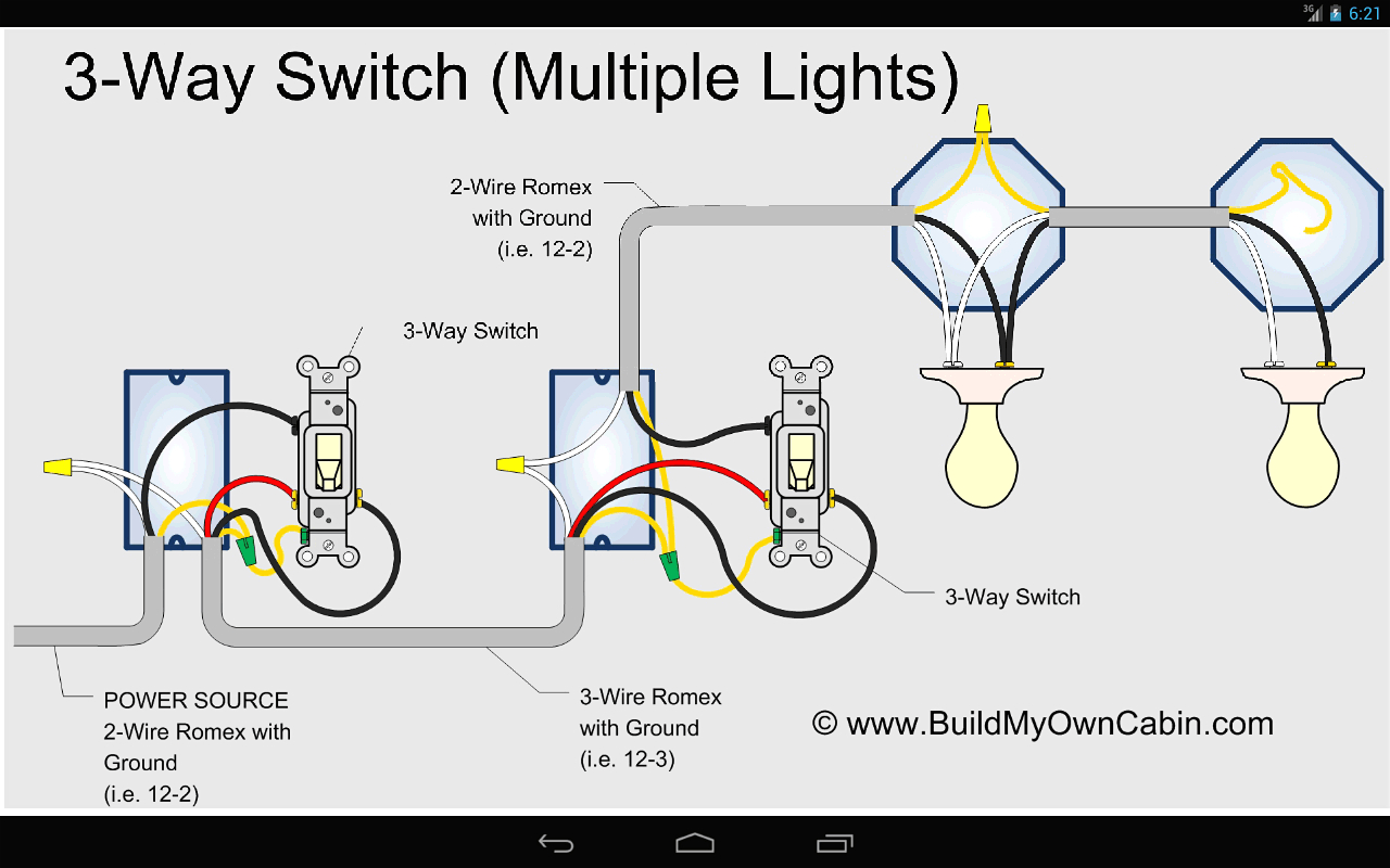
Wiring diagram two light switches one power source. As with all 3 way circuits the common on one switch is connected to the hot source wire from the circuit. Fig (a) is the two way light switch mechanism, fig (b) is the single gang switch face and fig (c) is the single gang two way light switch.
This means that you will have black red white and bare. The red wire is the ungrounded hot conductor from one switch while the black wire is the ungrounded hot conductor from the other switch. Ceiling fan with light kit wiring diagram.
Ceiling fan wiring (two switches) this ceiling fan wiring configuration is quite common. The national electrical code requires 2 cubic inches inside the electrical box for each #14 conductor. Suggested electric fan wiring diagrams converting a 12 volt switch into a ground switch these diagrams show the use of relays, on/off sensors, on/off switches and on/off fan controllers.
A two wire configuration uses two switches and two line wires each to control power to a fan and lights. A seperate wire then goes from ceiling fan 1 to ceiling fan two. Connect the 2 ground wires with a fourth wire nut.
I found no other connections. The wire goes from the breaker to a junction box branching into two separate lines. Multiple receptacle outlets can be connected with lighting outlets as depicted in the above light switch wiring diagram.
This lets you turn the fan on and off with the wall switch (along with the light). The above light switch wiring diagram depicts the power from the circuit breaker panel going to an electrical receptacle outlet and then continues to the next outlet and then to a single pole wall switch and then to another outlet. As a rule, the fan 's outer cover is held in place by three or four screws around.
This wire is also called the ground wire. This wire is critical as this wire saves the fan from having power swells. Car electric fan wiring diagram electric fan electricity.
A fan speed switch is typically connected to the black wire at the wall switch box and the black wire of the ceiling fan. Wiring schematic diagram for fan connection from two control switches. The hot and neutral terminals on each fixture are spliced with a pigtail to the circuit wires which then continue on to the next light.
Ceiling fan wiring diagram (two switches). One gang two way switch wiring. It switches power for both the fan and the light kit from the wall switch.
This diagram illustrates wiring for one switch to control 2 or more lights. The supplied diagram below using dual relays with a single temp sensor is both the most reliable and easiest method we've found for wiring dual fans. But the majority of fans are wired to work only alongside the bathroom light which can be really wasteful.
Simply connect the black wire with the electric motor and take out the red wire if your fan doesn’t have any lighting fixture. One gang two way switch. Line 2 goes to the livingroom wallswitch, then separate line from the wallswitch to ceiling fan 1.

Ceiling Fan Wiring Diagram Ceiling fan wiring, Diy

How To Wire 2 Separate Single Pole Switches To 2 Separate

Wiring 2 Ceiling Fans With 2 3 Way Switches Electrical

How To Wire Ceiling Fan With Light Switch YouTube
Ceiling Fan Wiring In New Construction Electrical DIY

Removing One Of Two Fans On One Switch... Electrical

electrical How can I rewire my bathroom fan, light, and

Two Ceiling Fans, Two Switches, One Breaker Electrical
Wiring Two Lights To One Switch Diagram Wiring Diagram

2 Way Light Switch Wiring Diagram House Electrical

exhaustfanwiringsingleswitch Bathroom fan, Home

How To Wire A Ceiling Fan With Two Switches Diagrams

Removing One Of Two Fans On One Switch... Electrical

Ceiling Fan Light On Dimmer Switch, Fan On Normal Switch

How do I wire a combination 2 single pole switch for a

How To Wire A Ceiling Fan With Two Switches Diagrams

Ceiling Fan Wiring In New Construction Electrical DIY
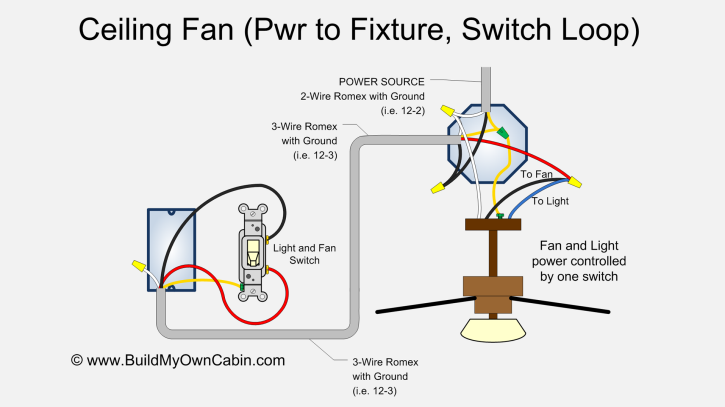
Ceiling Fan Wiring Diagram (Switch Loop)

How To Wire A Ceiling Fan With Two Switches Diagrams