
Ripple factor in a bridge rectifier. This is images about kohler rectifier wire diagram posted by jeremy kennard in kohler category on oct 26, you can also find other images like wiring diagram, parts diagram, replacement.
4 Pin Regulator Rectifier Wiring Diagram easywiring
There’ll be principal lines which are represented by l1, l2, l3, and so on.

4 wire rectifier wiring diagram. The best unusual is always to use a verified and accurate 5 wire regulator rectifier wiring diagram that’s provided from a trusted source. Make sure to find a solid ground. A few notes i pulled this schematic out of an older scooter repair manual.
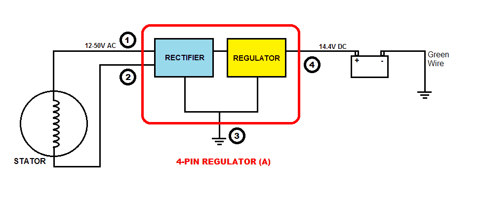
Simple 4 wire alternator wiring diagram. 4 pin regulator rectifier wiring diagram. Wingsmoto rectifier regulator 4 wires voltage atv gy6 50 cc scooter.kohler rectifier wire diagram:
Mount new part where the old rectifier was. 4 pin regulator rectifier wiring diagram from. Connect the positive (+) from your bike’s battery to each of the three alternator wires, one at a time.
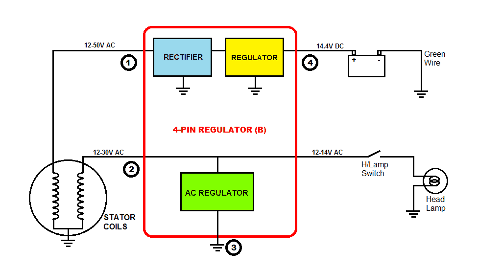
The circuit diagram below shows a half wave rectifier with capacitor filter. Buy voltage regulator rectifier for kohler 41 s 41 s 25 s: Connect to positive(+) battery terminal, and to positive(+) wires of all accessories on the lighting circuit.
Occasionally, the cables will cross. You need a lighting coil to supply an ac current that the rectifier will convert to a dc. I highly recommend using a voltmeter to test the voltages throught the rev range of the motorcycle before connecting anything to avoid.
As stated earlier, the lines at a rectifier regulator wiring diagram signifies wires. In each case, the test light should light up. List everything you need to run have a couple of spare circuits just in case and you are about 14 way there.
Excerpted from a cb750550 wiring diagram. Lock the rectifier into position by pushing the rectifier handles towards the shelf. The 10 100 regulator is connected to the harncss via the 3 single wires with spade terminals.
However, it doesn’t mean link between the cables. Pitbike rectifierregulator wiring diagram duration. 6 wire rectifier schematic 6 pin regulator rectifier wiring provided below is an online pdf document for lamberts bikes 4 pin regulator rectifier wiring diagram.
Motorcycle regulator rectifiers 5 wires plug for yamaha fzr600. 3 phase 6 wire motorcycle regulator rectifier wiring diagram pdf. (plastic 4 pin terminal + 4 male spade terminals included.) 3 wire stock rectifier.
Image result for 12v rectifier regulator wiring diagram regulators power source wire. Green and white are the same, but the diagram reversed red and yellow. Slide the rectifier until it connects to the rear of the shelf.
View lamberts bikes 4 pin motorcycle regulator rectifier wiring diagram. Adding a regulator rectifier to an outboard motor so you can charge a battery is a relatively simple job. Replacing the 100 voltage regulator on outboard motors with a 4 mercury outboard rectifier wiring diagram.
Regulator rectifier diagram here you are at our site this is images about regulator rectifier diagram posted by maria nieto in wiring category on may 08 2019. Wiring diagram regulator rectifier full adding a battery to my startv bike 250cc gy6 harley wire 4 lawn mower atv 110cc pin half wave 12v understanding motorcycle voltage 750 regulater honda cb 3 phase 6 hd 2xchinese scooter 49cc mini chopper data vz 2185 garmin striker lighting stator 1 vs 2. Panel where the rectifier are open causing high ripple or a c voltage while charging volts and amps are still.
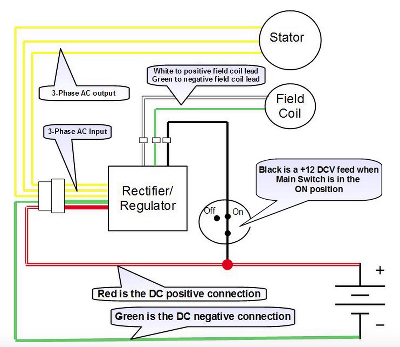
The coil in the diagram is shown attached at one end to earth, then just a few coils up is the green wire take off, then close to the end of the coil is the yellow with white tracer take off and right at the end of the coil is the yellow wire take off. Connect the 2 heavy red wires and the other end of the heavy dark brown wire from steps 4 and 5 above together. Use included wire with eye terminal to ground out the green wire on the regulator rectifier.
Connect to lighting leads from stator. Regulator rectifier wiring kzrider forum kz z1 z motorcycle enthusiast s. 6 wire regulator rectifier wiring diagram.
Many rick s motorsport electrics rectifier regulators eliminate what is commonly referred to as a signal wire on oe pieces. 4 wire regulator rectifier wiring diagram. Wiring diagram book a1 15 b1 b2 16 18 b3 a2 b1 b3 15 supply voltage 16 18 l m h 2 levels b2 l1 f u 1 460 v f u 2 l2 l3 gnd h1 h3 h2 h4 f u 3 x1a f u 4 f u 5 x2a r power on optional x1 x2115 v 230 v h1 h3 h2 h4 optional connection.
Asking for a simple diagram is like asking how long is a piece of string. The bikes wires are 3 yellow a red and a black. Wiring diagrams are made up of two things.
Wiring for small batteries under 4 ah: The casing does not need to be grounded. With this kind of an illustrative guide, you are going to be capable of troubleshoot, stop, and total your projects with ease.
In addition to wiring diagrams these guides also provide information on alternator identification and procedures for an engine. Yamaha outboard rectifier wiring diagram. Simply plug the connector onto the 5 pins row and make sure that the pin assignments and wire assignments are matched correctly.
Wave rectifier full wave rectifier ac dc. Buy 4 wires voltage regulator rectifier electrical voltage. Sample motorcycle wiring diagram included in this shipment and dictionary of automotive terms a teacherweb.
16 motorcycle rectifier circuit diagram motorcycle wiring. Injunction of 2 wires is usually indicated by black dot at the junction of two lines. Open the rectifier handle (35 to 40 degree angle) and place the rectifier into the mounting slot.
A good, conventional company that has a. Trail tech stators have yellow lighting leads.
bike rectifier circuit diagram Wiring Diagram and Schematics
4 Pin Regulator Rectifier Wiring Diagram Collection
Rectifier Wiring Diagram honda cb750k ltd 1979 usa spec


Led Diode Wiring Diagram Wiring Diagram
Understanding Motorcycle Voltage Regulator Wiring

diode relay wiring diagram Wiring Diagram and Schematics
Aftermarket Honda Regulator Rectifier OEM Style Honda

Voltage Regulator 4 Pin Regulator Rectifier Wiring Diagram

12 Volt 4 Pin Regulator Rectifier Wiring Diagram For Your
Understanding Motorcycle Voltage Regulator Wiring

Gy6 4 Pin Cdi Wiring Diagram Wiring Diagram

bridge rectifier circuit diagram and waveform Wiring
bike rectifier circuit diagram Wiring Diagram and Schematics

Yamaha Rectifier Regulator Wiring Diagram Wiring Diagram

4 Wire Rectifier Wiring Diagram Filter Capacitor

4 Pin Regulator Rectifier Wiring Diagram easywiring
bike rectifier circuit diagram Wiring Diagram and Schematics


Bridge Rectifier Circuit Diagram Wiring Diagram

Bridge Type Diode Diagram Wiring Diagram