Never connect the ac motor drive output terminals ut1 vt2 and wt3 directly to the ac mains circuit power supply. 10.7 drive status digital outputs.
3 x jumper wires wiring diagram.

Ac drive control wiring diagram. See paragraph t for frame size assignments of type codes. Opening frame size r3 and r4 units. Siep yaip1b 01b ac drive bypass for industrial fans and pumps technical manual models:
On the next figure, we show the durapulse wiring diagram for this specific application. 2 press the retaining lever inside the hole located at the top of the drive. Wiring diagrams show the connections to the controller.
In the lower right corner of the operator interface are the four cursor keys, indicated as or or (item 2 of figure 9 ). .17 11 scl/scm control wiring diagrams. 1 remove the control panel if needed.
The ach is an variable frequency ac drive designed specifically for the hvac market that achieves control circuit connection diagram for each macro. They show the relative location of the components. Wiring diagram template.inline application program acs firmware manual this manual includes information on:
The vfd main circuit terminals shown as below figure. The acs adjustable speed ac drive should only be installed by a power circuit terminals u1, v1, w1 and u2, v2, w2 and, depending on the following diagram shows the terminal layout for frame size r3, which,. Contributor to the sport since 2002.
This wiring diagram was prepared for you by amitava sen from kolkata india. Basically, a setup of ac drive for an application includes three major steps, namely control wiring, power wiring and software programming. A servo motor will have mainly there wires one is for positive voltage another is for ground and last one is for position setting.
To purchase any saftronics drives or information regarding saftronics drives and accessories, contact us at: Wiring up an abb acs i/o for abb standard macro presented by katie rydzewski for galco tv. Figure c.1, network wiring diagram, updated.
Wait ten minutes for the capacitors to discharge to safe voltage levels before opening the ac motor drive. Yaskawa ac drive p1000 manual no. Design, the powerflex 4m ac drive is the smallest and most cost effective member.
I1 preface yaskawa manufactures products used as components in a wide variety of industrial systems and equipment. Ensure the end user receives this manual. Gs20x ac drives installation instructions.
Call for availability of drives, and freight options. They can be used as a guide when wiring the controller. Only qualified personnel familiar with ac motor drives is allowed to perform installation, wiring and commissioning.
Strip and connect the individual control wires to the drive terminals. 1 remove the control panel. Once the power and control wiring is done, we have to configure the ac drive parameters appropriate to the application requirements through software programming, removable keypad, or remote operator panel.
The control loop shall have the proper values of p, i, and d to generate the control output cv, which is the frequency command to the drive. (1) the vfd's three phase ac input terminals (r/l1, s/l2, t/l3) the power line's input terminals connect to 3 phase ac power through line protection or leakage protection breaker, it does not need to consider the connection of phase sequence. Construction of ac servo motor.
Make sure that the power is off before doing any wiring to prevent electric shock. 3/4 to 500 hp to properly use the product, read this manual thoroughly and retain for easy reference, inspection, and maintenance. The following two paragraphs will help you identify the right type of servo motor for your projectsystem.
Buy the items featured in this video at.abb acs wiring diagram abb acs 01 user manual pdf download view and download abb acs 01 user manual online drive low voltage ac drives acs 01 power supply pdf. 1 the vfd s three phase ac input terminals r l1 s l2 t l3 the power line s input terminals connect to 3 phase ac power through line protection or leakage protection breaker it does not need to consider the connection of phase sequence. All prices are subject to change without notice.
1/2 to 100 hp 480 v: Vfd start stop wiring diagram. Figure 8 opening the frame size r1 and r2 drives of type ip 21/nema type 1.
V primary, v secondary only. For additional powerflex 4 and 40 data and general drive information, refer to wiring and grounding guidelines for pwm ac drives the block diagram. The drive will run to regulate the speed of fan to just deliver the right air flow.
.18 11.1 scl/scm terminal strip.
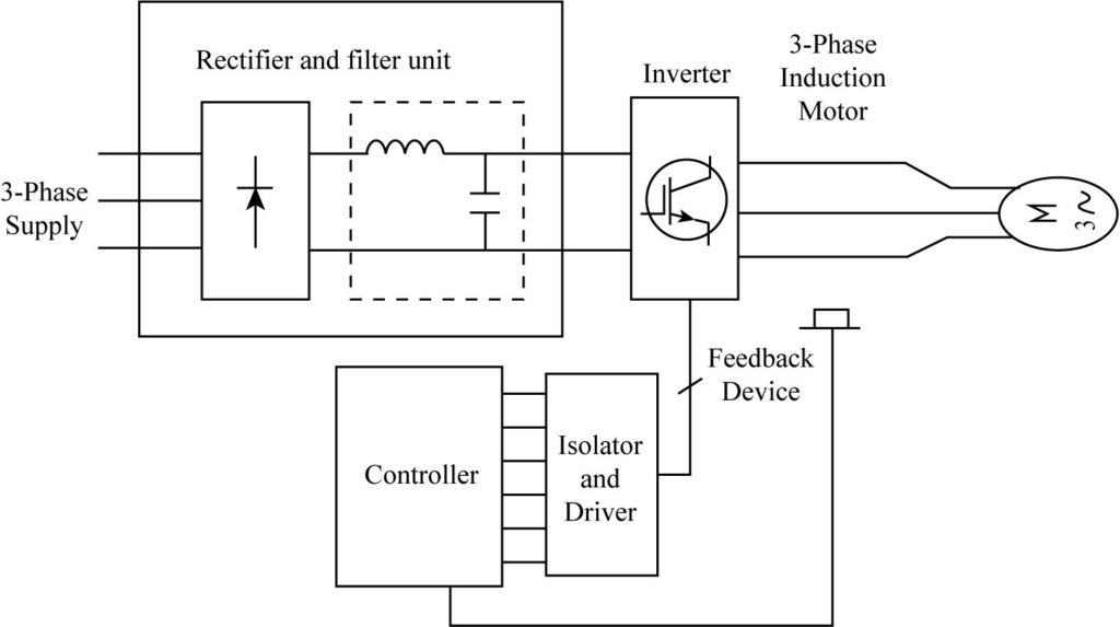
vfd schematic diagram and control Wiring Diagram and
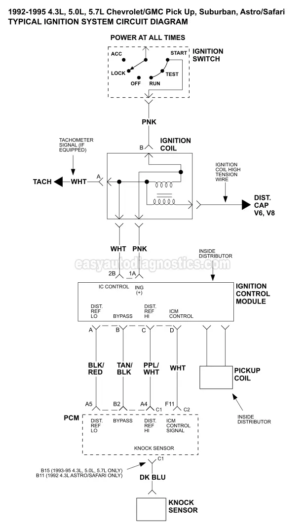
1995 chevy silverado 1500 wiring diagram Wiring Diagram
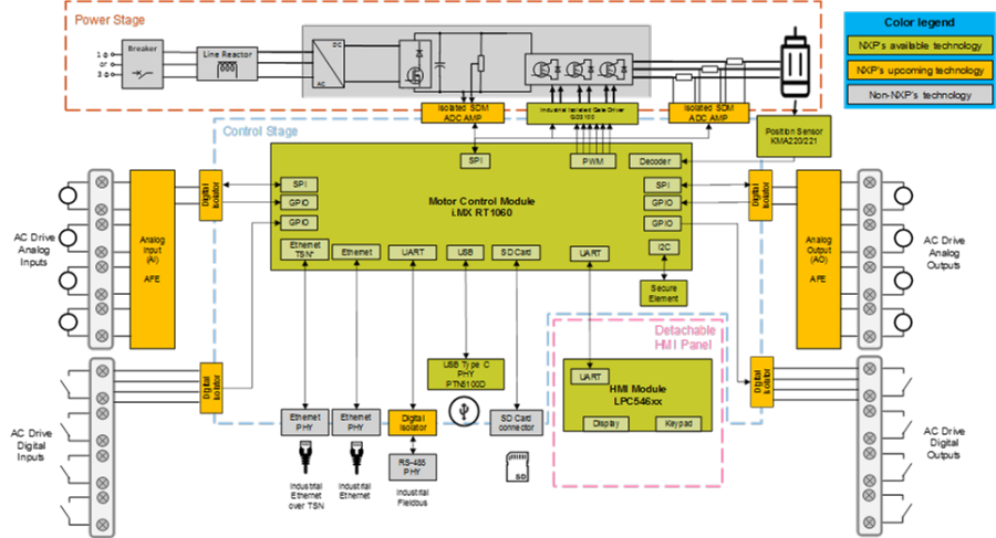
Need To Design an AC Drive with High Precision and

Wye Delta Starter Wiring Diagram All About Information
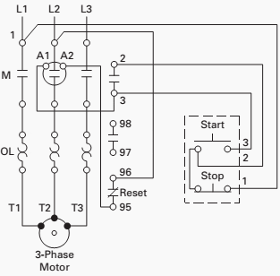
control wiring diagram of 3 phase motor Wiring Diagram

range hood wiring diagram IOT Wiring Diagram

2006 Honda Civic Ac Pressure Switch

AC Drive 6 Control wiring شرح مغيرات السرعه YouTube
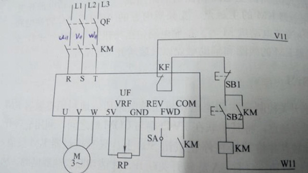
3 phase forward reverse motor control circuit diagram

wiring diagram for kit car IOT Wiring Diagram
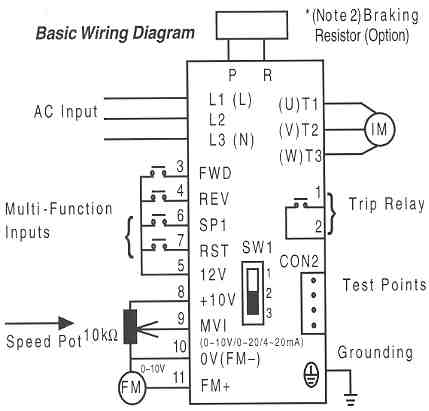
vfd schematic diagram and control Wiring Diagram and

Control Wiring Diagram Of Vfd Wiringpedia
vfd schematic diagram and control Wiring Diagram and
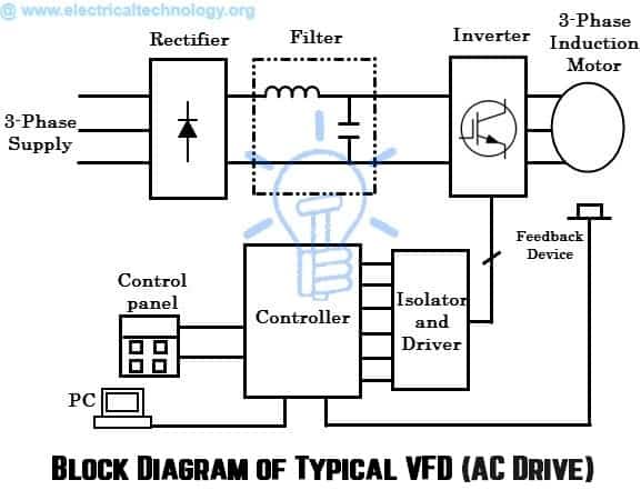
What is AC Drive? Working & Types of Electrical Drives & VFD

Vfd Motor Control Circuit Diagram Pdf Wiring Diagram
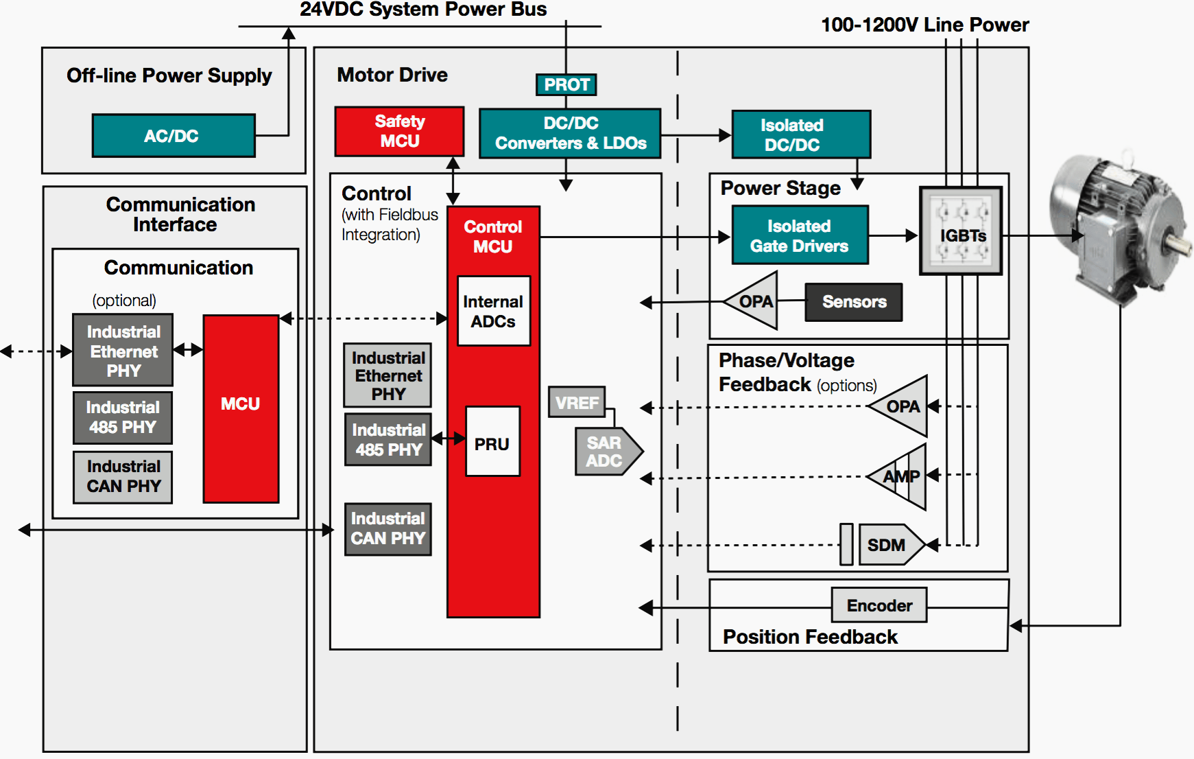
Yup, it's the motor drive that makes systems in motion all
