
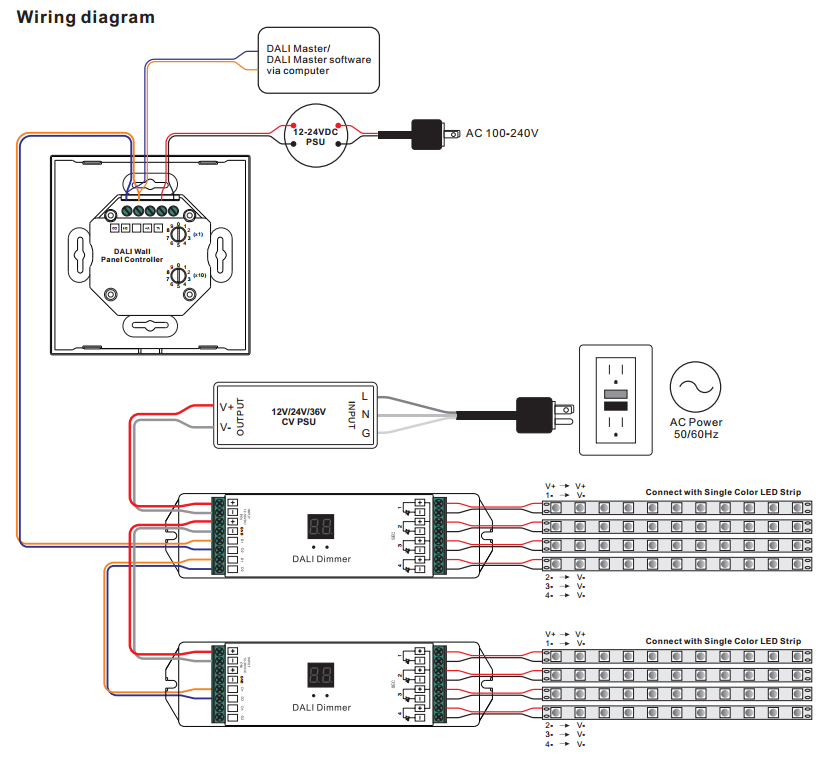
The purple and grey wires are separate from ac or dc power wiring. Long press the push dim switch (>0.5s) to dim the brightness of light;
Wiring Diagram For Auto Dimming Mirror Tuts Endless

Bright leds are o dim leds are x in descriptive form, all the freezer leds are fine.

Dim and bright wiring diagram. Check out our wiring wizard for step by step instructions videos and wiring diagrams including 3 way for installing a dimmer. Adjusts the light level of the fixture. If you continue to hold the left half of the dim/bright bar, the lights will dim to minimum level and then turn off.
Looking at the wiring diagram attached, i don't see know that wiring is your issue. Din standard 72 552 establishes the terminal numbering system that's used for any wiring diagram or vehicle wiring that conforms to din specifications. The terminal codes are not wire designations, as devices with differing terminal codes can be connected to the opposite ends of a single wire.
Fixed kitchenaid refrigerator kbsn602epa01 some dim leds, some bright, looking for wiring diagram or which led module to replace You would need to run low voltage wiring from the fixture back down to a. The terminal codes are not wire designations, as devices with differing terminal codes can.
Wiring diagram product size feature •safe and reliable full isolation design •triac dimmable and mosfet dimmable •leading edge dimming and trailing edge dimming both available •great compatibility with a variety of remote controls •innovative minimum brightness setting function •to dim and switch single color dimmable led lamps. When you have wiring that is getting old and has higher resistance, it basically steals some of that voltage that the bulb would use to make it as bright as possible which causes it to be dim. A diagram that represents the elements of a system using abstract, graphic drawings or realistic pictures.
Led magazine) this is an improvement over triac dimmers that are actually powered by the current flowing through them that is drawn by the led load (see figure 5). Long press the push dim switch (>0.5s) to dim the brightness of light; Push dim function instructions a.
When the light being turned off, long press the push dim switch can turn on the light and adjust. The dimmer 2 will be activated always at previously set brightness level. Mounting clipsal standard range products use the 30 series switch.
If you prefer, you can simply run the green wire to any convenient good ground. This arrangement is provided for easy reference when dealing with a circuit wired in this arrangement. When the load pulls less current than the minimum triac holding
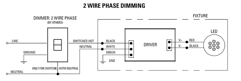
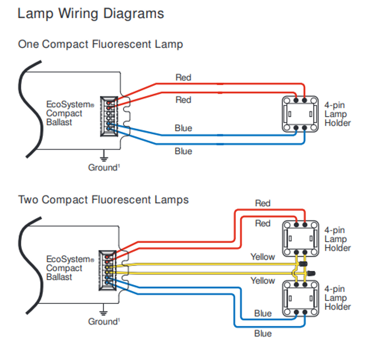
Wiring diagrams are examples of typical installations intended to illustrate the number of wires that must be run to fixture. Less voltage getting to the bulb means it is not as bright. Short press the push dim switch (<0.5s) to control the lamp on or off c.
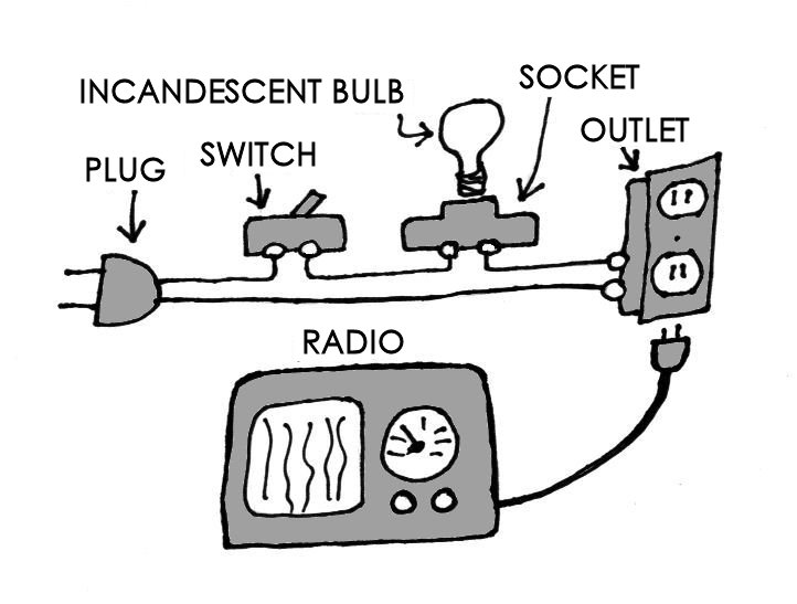
Electrician circuit drawings and wiring diagrams youth explore trades skills 3 pictorial diagram: The dimming direction will change 4 way dimmer switch wiring diagram.
In rc, the middle left one is completely out. Voltage o sparking generator black. Bright/dim low switch white 9 10 15/54 pa pa n n 57 58 56 flash switch high beam fuse #4 from 2nd position right 1st position pulled pa 57 30 c a b left 1st position right ign switch red/yellow white blk 54 blk/blue 15 56a 31 red red 1 indicator 5500912 std as of door switch black (2) 2 1 black/mauve black/mauve to 018971 black/white fm 018972 (high) (maintain) 3 4 (low).
These diagrams are not intended to specify all equipment necessary for a given dimming circuit. A diagram that uses lines to represent the wires and symbols to represent components. When lights are off you can change the light level that the lights will turn on to using the dim/bright bar.
All the other x lights are merely dim. Ecue ruck r distributor regulator o battery starter switch starter motor tracer horn button ammeter direction indicator Wiring diagram symbols wiring diagrams use simplified symbols to represent switches lights outlets etc.
The purple and grey wires are separate from ac or dc power wiring. Dim headlamp contact breaker direction indicator filament dim bright side r.h. In the diagram below a 2 wire nm cable supplies power from the panel to the dimmer box.
One feeding the dim filament, one feeding the bright filament, and one ground. The dim lights are the top rc led, plus the lowest one on the left, and all three on the right. The lower the voltage input, the more the fixture will dim.
The dimming direction will change every time after pressing switch d.
16 Lovely Tridonic Switch Dim Wiring Diagram

Forward Phase Dimming Solutions USAI
0 10v Dimming Wiring Diagram Atkinsjewelry

Wiring Diagram PDF 0 10 Dimming Ballast Wiring Diagram

Low Voltage Led Dimmer Wiring Diagram Wiring Diagram Schemas
30 Lutron Dimming Ballast Wiring Diagram Wiring Diagram List


Led Dimming Wiring Diagram 12
Dim Engine Diagram Wiring Diagram

Dimming Ballast Wiring Diagram Free Wiring Diagram

32 0 10 Volt Dimming Wiring Diagram Wiring Diagram List

Dim Bulb Tester Wiring Question Audiokarma Home Audio
Trailing Edge Dimmer Wiring Diagram

0 10v Led Dimming Wiring Diagram Wiring Diagram
D Series Touch Panel Dimmer Switch Wiring Diagram
0 10V Dimming Wiring Diagram Yv 6552 0 10v Dimming Led


33 0 10v Dimming Wiring Diagram Wiring Diagram Database
Step Dimming Ballast Wiring Diagram General Wiring Diagram
Dim Engine Diagram Wiring Diagram

Fluorescent Dimming Ballast Wiring Diagram For Your Needs
