We then run a jumper wire from the electric brake power wire to the right side brake assemblies see photo. Each part should be placed and linked to other parts in specific manner.

Brake Controller Installation Kit for a 1999 Toyota
Break away systems may be added to the service brake circuit.
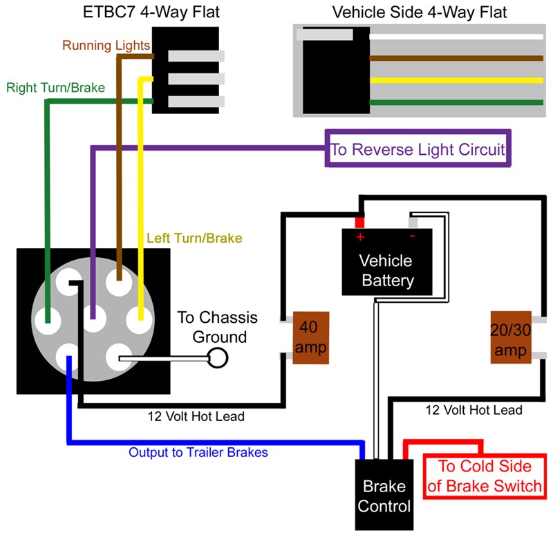
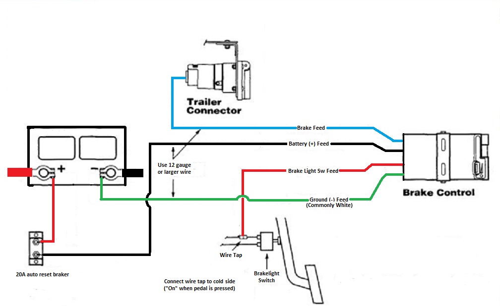
Electric brake controller wiring diagram. Electric brake controller wiring diagram tekonsha prodigy p3 wire diagram electrical problems universal installation kit for trailer brake controller 7 way rv and 4 way flat 10 gauge wires e trailer installation trailer plans This makes the process of building circuit simpler. This 7 pin trailer wiring diagram electric brakes model is more suitable for sophisticated trailers and rvs.
Primus utilizes the primary sensor technology from. Primus iq is a totally proportional electric trailer brake control. Most brake controllers are adjustable.
Can you get me a wiring diagram for primus iq brake controller? Connect the brake controller power harness white wire to the negative terminal on the vehicle battery. Wiring diagram trailer electric brakes valid wiring diagram trailer.
This 7 pin trailer wiring diagram electric brakes model is more suitable for sophisticated trailers and rvs. Electric brake controller wiring diagram. On alko electric brakes wiring diagram.
The black wire coming out of the brake controller is the brake controller power supply. A second tail needs to be soldered and spliced into the sensor on. Do not disturb the position of the switch.
This can be helpful for each the individuals and for professionals who are seeking to learn more regarding how to established up a functioning atmosphere. Auxiliary connection is optional, it may be connected to any 12v to 24v constant power source or left unconnected. Wiring diagram comes with a number of easy to adhere to wiring diagram instructions.
Important facts to remember 1. Read and follow all instructions carefully before wiring brake control. Secure the brake controller harness with cable ties (not supplied) away from any moving parts, sharp edges or hot surfaces at 200mm intervals.
Electric brake controller wiring diagram. Hayman reese electric brake controller wiring diagram wiring diagram is a simplified tolerable pictorial representation of an electrical circuit it shows the components of the circuit as simplified shapes and the capacity and signal contacts between the devices. The brake control must be installed with a 12 volt negative ground system.
Redarc brake controller wiring guides. As stated previous, the lines at a prodigy brake controller wiring diagram represents wires. However, it doesn’t mean connection between the cables.
Use a 4mm x 2 core cable for your active and earth wires to the brakes separate from wiring used for lighting etc. A wiring diagram is a streamlined conventional. Electric brake controller wiring diagram.
Wiring instructions for electronic brake controls p/n 4399 rev k generic wiring diagram read this first: Wiring electric magnets with cable size of 6mm for the single axle 2 magnets and 5mm for tandem axles. To make wiring a brake controller easy and cost efficient we sell a brake controller wiring kit that does both 20amp and.
How electric brakes work trailer brake wiring diagram wire a for control diagrams etrailer com husky 30798 plate lights installing on your controller installation and problem forest question keystone rv assemblies parts online with 7 way plug general dexter white to install an braking guidelines cm breakaway. Using an eb24a to charge a ba6000. Test the electric brake controller function using a light board or multimeter.
Keep these instructions with the brake control for future reference. The brake control must be installed with a 12 volt negative ground system. This controller features a patented accelerometer design which senses the deceleration of the towing vehicle and sends a proportional voltage to the electric trailer brakes.
The 12 volt hot lead and the brake controller power supply. One end of the wiring harness plugs into the vehicle’s factory harness under the dash, and the other end plugs into the brake controller. The brake control must be installed with
The following diagram is a general guide for wiring common brake controllers into cars. There are now two wires connected to the positive post: The diagram offers visual representation of an electrical arrangement.
Injunction of 2 wires is usually indicated by black dot on the junction of two lines. Plug in the brake controller. Electric brake controller wiring diagram.
Occasionally, the wires will cross. Dexter electric brakes wiring diagram. It represents the power circuits factors as simple forms, using the real power and terrain contacts between the two as colored circles.
However, this diagram is a simplified version of the structure. Make sure this fits by entering your model number. Learn correct wiring of redarc's range of brake controllers and accessories.
Assortment of electric trailer brake wiring schematic. Learn correct wiring of redarc's range of brake controllers and accessories. With the power sorted (but not connected to the battery) three more tails in the wiring loom need connecting.

Wiring Diagram Electric Trailer Brake Control Trailer

Trailer Wiring Harness With Electric Brakes Pilot 80550

Electric Brake Wiring Diagram Australia Home Wiring Diagram

Electric Trailer Brake Controller Wiring Diagram Trailer

Electric Trailer Brake Wiring Schematic Free Wiring Diagram

Agility Brake Controller Wiring Diagram 10
Electric Brake Wiring Diagram Australia Home Wiring Diagram

How to Install an Electric Brake Controller It Still Runs

Elecbrakes Bluetooth Electric Brake Controller

Electric Brake Controller Wiring Diagram Elecbrakes

Wiring Diagram For Electric Trailer Brake Controller

Wiring Diagram For Electric Brake Controller di 2020

Electric Trailer Brake Controller Wiring Diagram Trailer

Wiring Diagram For A Trailer Brake Controller Trailer

Trailer Electric Brake Controller Wiring Diagram Trailer
Installing Electric Brake Controls on 24 Volt Vehicles

Electric Trailer Brake Controller Wiring Diagram Wiring

Electric Trailer Brake Wiring Schematic Free Wiring Diagram

