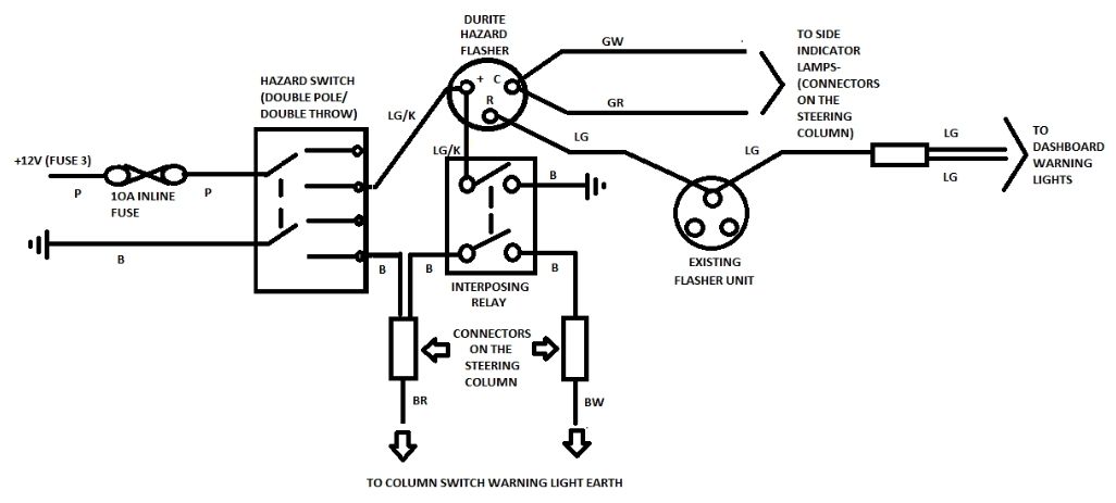
The flasher receives power from one of 2 fuses, depending on whether or not the hazard switch is operated. A wiring diagram usually gives opinion practically the relative turn and concord of devices.
Motorcycle Hazard Light Switch Wiring Diagram DINISAK
Wiring diagram for hazards and indicators.

Hazard switch wiring diagram. The hazard switch gets power from two sources. Full membership is only $30 pa and you will have full access to all of the tech manual including the linkage tour, critical to keep your car in tip top condition, the pagoda notes from no. Connect terminal l of hazard warning switch to left side.
A fuse clip and push on terminal has been provided for this. 12v hazardous warning lights switch. 4 mount the hazard switch (photo 4) in a convenient location.
This is the same connector that attaches to the steering column harness (i.e. Illuminated push button hazard switch rectangular. Connect terminal 49a of hazard warning switch to flasher unit terminal no.
49s to cable from flasher unit. 7 x 6.3mm blade terminals. Hi i am after a simple if there is one wiring diagram of how to wire up indicators and hazard light on a classic that only has trafficators,flags that flip up.i have googled but no luck.thanks all.
The hazard light switch has multiple possibilities including a off/shut. What fuse is for the hazard switch and central locking button? Externally, the only difference is in the connection for the dash indicator.
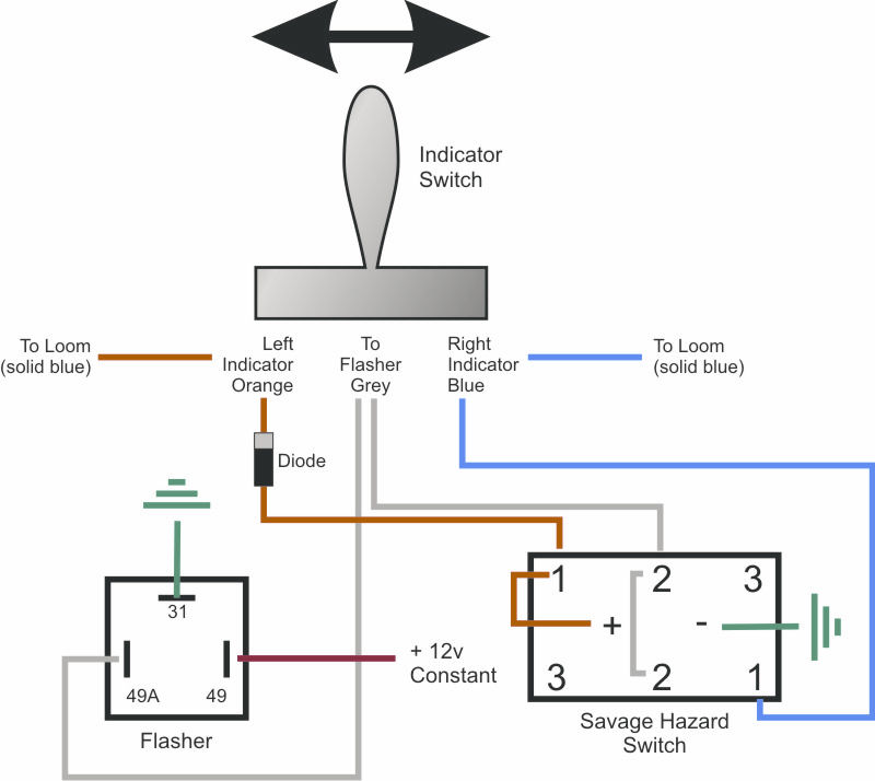
Pink 12 volt ignition feed connect. You need the six pole savage switch for hazard , the six pin connection mounts on the two pin switch. So i am wiring up my hella micro de's to the isuzu factory fog light switch diagram, only to discover that my foglight switch was not the same as scott's.
Autozone repair guide for your wiring diagrams hazard switch () turn and hazard warning light wiring diagram. Push on, push off function. Connect the cut end of cable to the hazard warning switch as follows:
The terminals go to the corresponding wire colors: This is where the wires from your lights to the hazard switch should come from. Wiring diagram in the catalogue.
Two wires will need to be run from there to this new dash switch. Connect the cables of the hella hazard warning switch using the connectors supplied, as follows: This wire is connected to terminal v & 31 on the brake
Turn signal switch/hazard switch wiring type 1 std beetle late 68 thru early 71 (vin 1x8 381 367 thru 1x1 2799 842) karmann ghia late 68 thru 1971 (from vin 148 381 367) (71 models only) *view shown is from the rear side of the switch* 49a 31 49 p(kbl) flasher relay, 4 terminal 15 + 30 49a 54 54f rl hazard light switch brown/white brown to terminal s on headlight relay I don't have a diagram for the defrost switch, but if you look inside the back of the switch housing by the terminals you should see the letters b, d, j, u. Turn signalhazard flasher circuit diagram.
2fee2 hazard switch wiring diagram motorcycle wiring resources 1fdc wiring diagram for motorcycle hazard lights epanel ship from signal flasher motorcycle adjustable led blinker relay hazard double signal White), thus making it easier to differentiate from the real hazard switch in the dark. Fuse #11 is constant power (terminal 30) for the hazard function, it also supplies power to the interior light.
Car hazard wiring diagram wiring diagram and schematics wiring diagram and schematics this place is a growing library of the schematics,. Route and attach the red wire marked “hazard b+ constant source” to a fused constant hot power source. 15 to cable from ignition switch.
In the second case the small bulb contained in the switch is on. Cut the active cable between the ignition switch and the flasher unit. Connect terminal r of hazard warning switch to right side flasher circuit.
This wire can be connected with the red wire in step 3. White tach sender wire connect to the ‘sender’ location on gauge. With internal 12v 1.2w bulb illumination.
Tan gas sender wire connect to the ‘sender’ location on gauge. If the turn signal work ok you may have a bad switch. Pilot neon light switch 1 needs an active neutral wire while the pilot light switch 2 dont require a neutral wire.
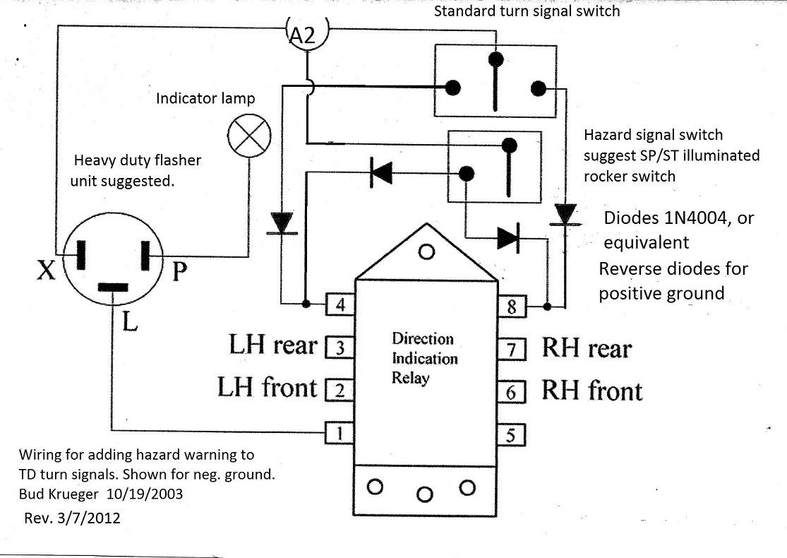
This diagram shows the turn signal flasher circuit in its simplest form: This manual applies to models. Isuzu vehicross hazard switch wiring diagram.
Connect terminal +30 of hazard warning switch to a fused terminal of the fuse box that is not ignition controlled. This video explains the wiring diagram for the central locking button on. Coloured wiring diagrams are here in the technical manual but they are only available to full members.
Fuse #9 supplies power (terminal 15) for the turn signals.
Brake Lights Wiring Diagram Wiring Diagram
Trillogy / Savage Hazard Switch Wiring Guide Page 3
Weekend 200NS hazard light project Ramblings of a
Hazard switch rocker


Wiring Diagram For Motorcycle Hazard Light Wiring

VOLKSWAGEN HAZARD SWITCH WIRING DIAGRAM WIRING DIAGRAM

☑ How Diode Work As A Switch

Isuzu Vehicross Hazard Switch Wiring Diagram
Hazard Warning Lights The 'E' Type Forum

Hazard Switch Constant 12v to Keyed Wiring Defender

Hazard Switch Kits
Hazard Lights


68 MGB HAZARD SWITCH WIRING?????? MGB & GT Forum MG
Savage/Trilogy Hazard wiring.....?!?! Tech Talk WSCC
19 New Hella Hazard Switch Wiring Diagram

Adding Hazard Warning to TD Turn Signals

Panel mounted push on hazard switch
Flashers and Hazards
TD5 Hazard Wiring Defender Source