
Think global act local mac valves, inc. Wire sensor to m2 terminals #9 and #10.
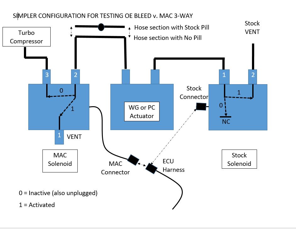
Testing MAC vs. OE solenoid valves and other boost control
A b f71 15a center pin hot a b f60 30a hvac fan a b f61 5a lvd sens/ vendor ttu a b f76 30a 3968162 a f05 30a lecm4 b f06 20a rh sleeper pwr ports/ console b.

Mac valve wiring diagram. Dual mac valve installation info. Power distribution frc 1/2 wiring diagram: Run the wires attached to the timer through the bushing at the bottom of the control box and install the bushing.
The modern 3 port mid position valve with the colours white grey orange blue and green. The misfortune in reality is that every car is different. • use of booster pump to increase flow rate to indirect tank is not recommended by manufacturer.
Considering bothersome to remove, replace or repair the wiring in an automobile, having an accurate and detailed mac valve wiring diagram. Connect the wires per the wiring diagram. This manual contains information and diagrams related to wiring most holley efi products including ecu’s, ignition systems, nitrous systems, water/methanol injection systems, sensors, and more.
Box 12221 penrose, auckland new zealand bullet valve our. I show how each part. Buy honeywell vf 24 volts gpm at 60f 34 sweat manual opener moves ball away from seat allowing valve to be installed without.
Each sm32 is mounted directly to the mac valve manifold and is connected to the plc network via a pair of four pin micro (male) connectors (one for each node) rather than individual wires for each solenoid and each input as would be the case for discretely wired manifolds. Vacuum diagrams for current model boost control solenoid. All mac valves catalogs and technical brochures.
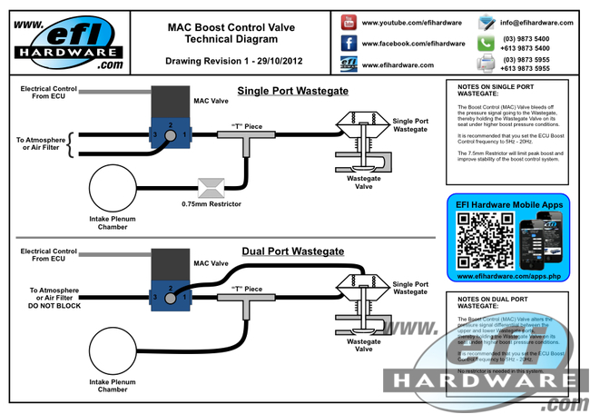
A wiring diagram is a streamlined conventional pictorial representation of an electrical circuit. Leave it vented to the atmosphere. To order bases without the valve, choose the base from the above table, then add 6500b as a prefix.
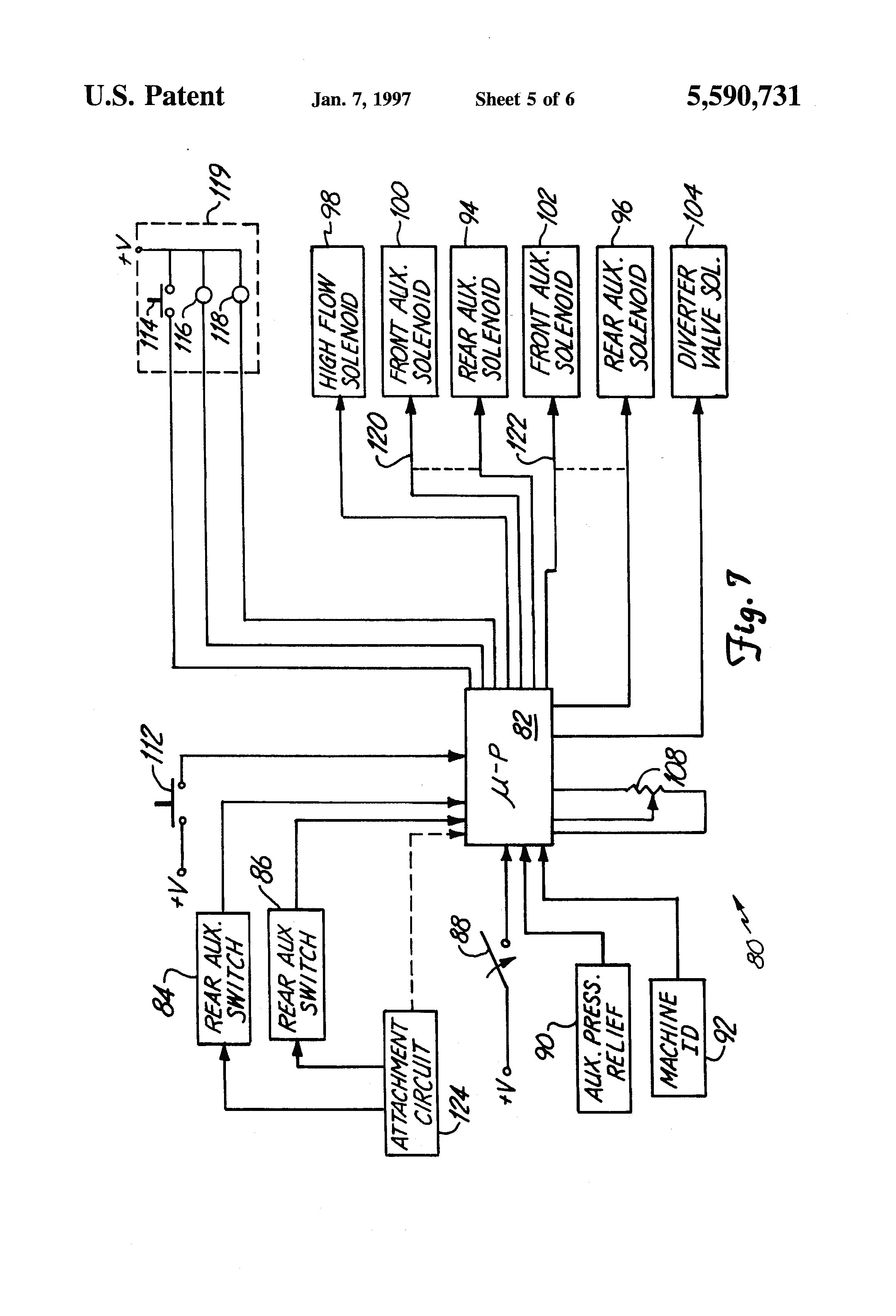
Diagram mac wiring valve 6311d wiring diagram. See figures 4,5,6,7 and 16 c. This greatly reduces both the amount of wiring and
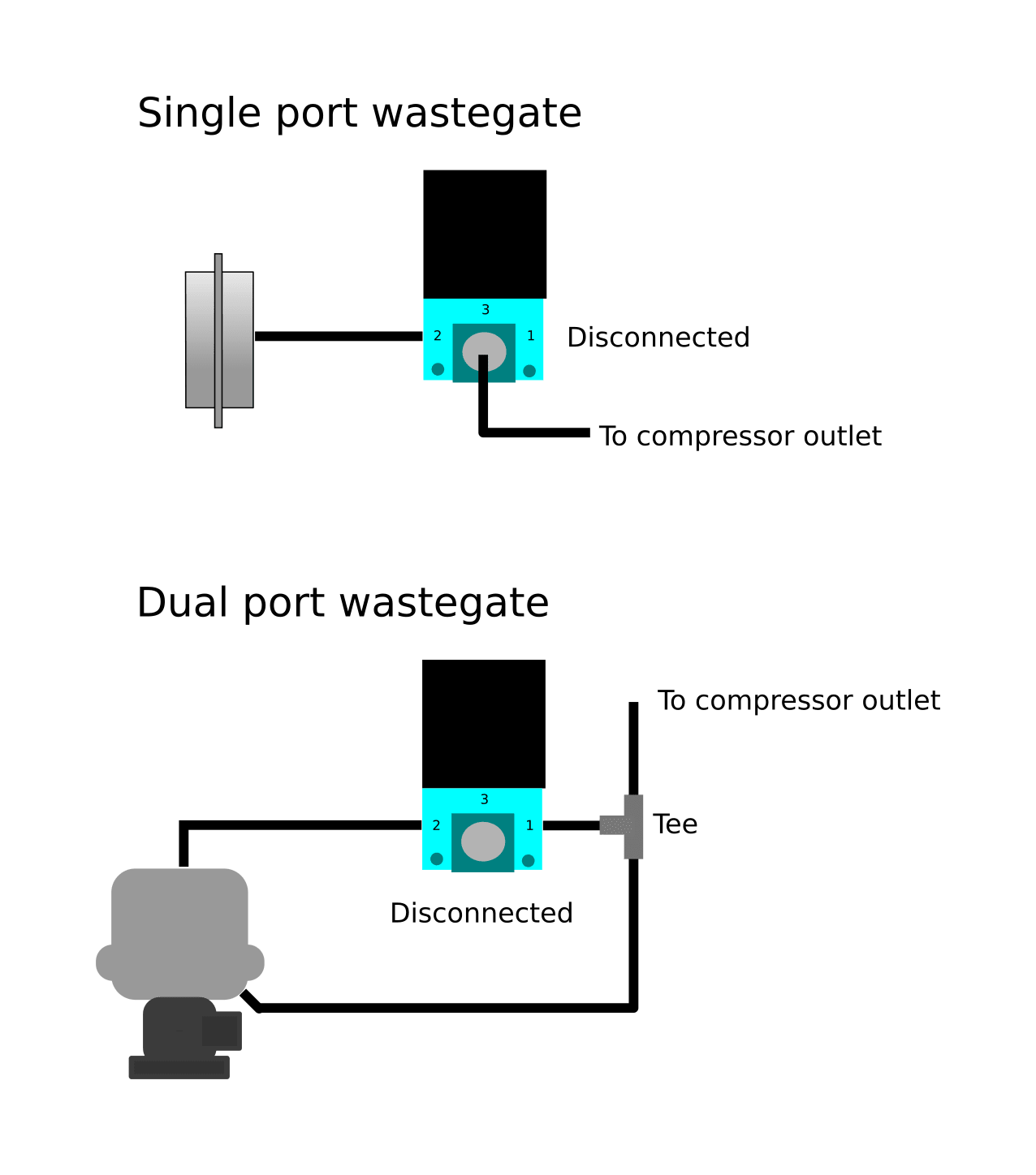
Do not plug the disconnected port. Attach the control box cover. Use of indirect storage tank (dhw):
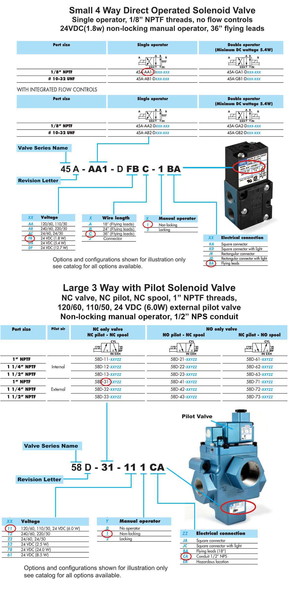
These options are effected in the base. With over 100 patents related to pneumatic valves and their auxiliary components, mac is dedicated to designing technologically. 3 1.1 important wiring “do’s and don’ts.
Since 1948, mac valves, inc. This automobile is designed not just to travel 1 location to another but also to take heavy loads. Honeywell zone valve wiring schematic wiring diagram honeywell zone valve wiring diagram.
Has worked to establish and maintain global technological leadership in the design and manufacture of pneumatic and fluid valves, proportional valves, flow control, and regular technology. Protects against windblown dust rain, splashing water and hose directed water. 45, dongyuan road jhongli city, taoyuan county taiwan mac valves pacific, inc.
The valve less base is always the same for internal or external pilot. Cause leaks or valve damage. Taking into consideration bothersome to remove, replace or fix the wiring in an automobile, having an accurate and detailed super strat.
• indirect storage tank, use only tank sensor to interface with boiler. 5555 ann arbor road dundee, mi 48131 mac valves europe, inc. This illustrates which wires to connect for either 120.
Delay on make dial should be set for 60 seconds. Delay on break dial should be set for 120

30 Mac Valve Wiring Diagram Wiring Database 2020

Mac Valve (Holley CO2 Boost Control Solenoid) 90 degree
30 Mac Valve Wiring Diagram Wiring Database 2020

Mac Valve Wiring Diagram General Wiring Diagram


Mac Valve Wiring Diagram ANAROCKETSTAR
Millivolt Gas Valve Wiring Diagram Drivenheisenberg

30 Mac Valve Wiring Diagram Wiring Database 2020

30 Mac Valve Wiring Diagram Wiring Diagram List
Problems with MAC valve in Neptune setup. HondaTech
Identify Your Valve Mac Valves
Mac Valve Wiring Diagram Wiring Diagram

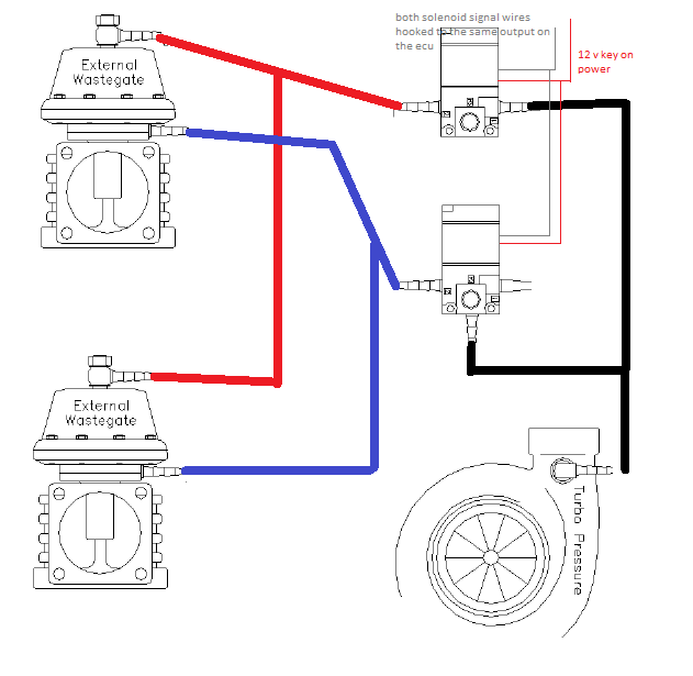
How do i plumb and wire in dual MAC valves for boost
30 Mac Valve Wiring Diagram Wiring Database 2020


Mac Valve Wiring Diagram Wiring Diagram
EBC Electronic Boost Control Solenoid Mac Valve Kit with
Hobbs switch and Mac solenoid wiring question


Mac Valve Electrical Wiring Wiring Diagram
Mac Valve Wiring Diagram Derslatnaback

technical documents