
Furuno usa supplies nmea approved components as follows. The reason for connecting via nmea0183 is that in a larger.
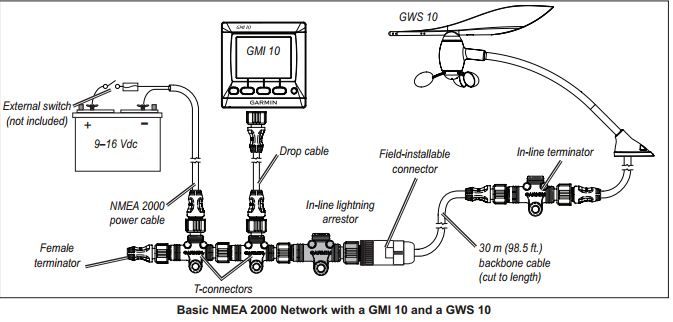
Installing the Garmin GMI10 Display Data Repeater on a boat

Nmea2000 backbone cable, 6m 1 ea.

Nmea 2000 power cable wiring diagram. Each node uses a one of two different, five pin circular connectors, just as some implementations of canbus. Add to cart find a dealer. A single network cable replaces a myriad of cables used by today’s methods of interconnection.
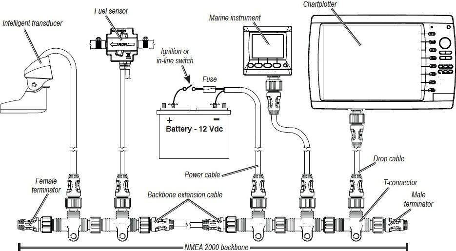
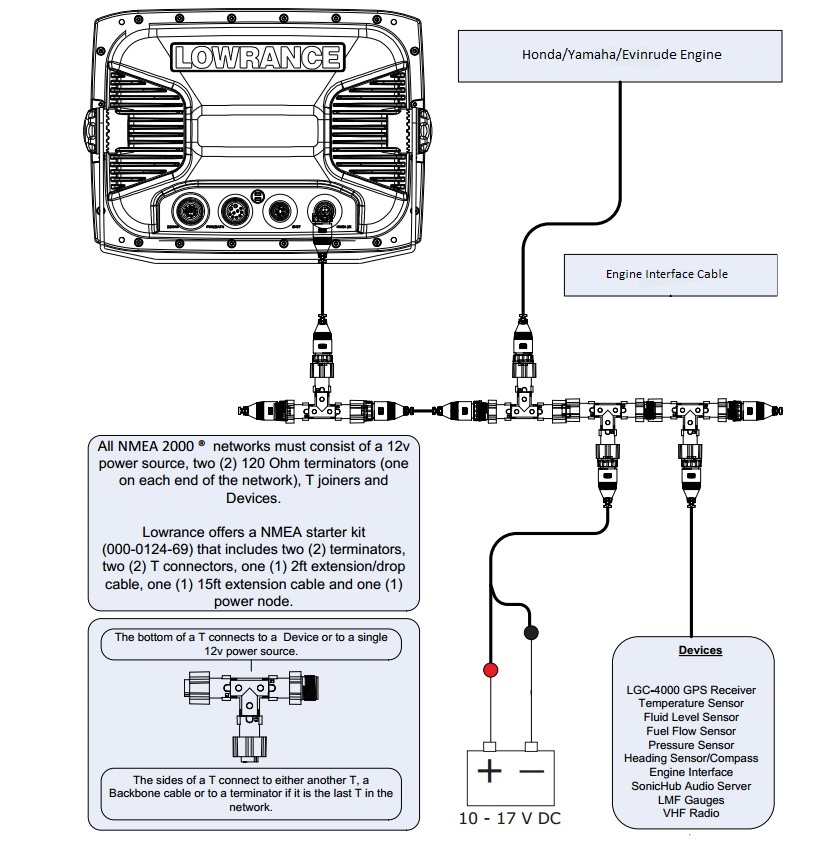
A backbone is simply a power cable that connects your nmea 2000 items of equipment. Even if you only have 1 item of nmea 2000 equipment then you will still need to get a backbone. Nmea2000 starter kit consists of nmea2000 drop cable, 2m 1 ea.
Check to see if an. Nmea 2000 devices connect to the backbone using a simple t piece connector. Use this diagram to connect the lvr to a lowrance gps unit that is not connected to a radar unit.
The red wire from the sensor cable will be connected to the red wire from the nmea 2000 cable. The nmea 2000 network accommodates navigation equipment, electrical power generation and distribution systems, engines and other machinery, piloting and steering systems, fire and other alarms, and controls. Courtesy garmin power up the network.
Foil (overall), foil (power pair), foil (data pair) power pair wire: This particular image (raymarine gps antenna wiring diagram raystar 120 gps. Garmin displays may also include additional nmea 2000 components (such as a power cable).
The nmea 2000 wiring colour system is standardised so the colours and pin numbers will be the same for any wire and connector combination that uses the same devicenet standard. One pair is red and black, the other is red/white and. Likewise, the black wire from the sensor cable will be connected to.
The nmea 2000® cable system includes five wires within a single waterproof cable: A wiring diagram is a simplified conventional photographic depiction of an electric circuit. Garmin nmea 2000 starter kit wiring diagram.
Garmin displays may also include additional nmea 2000 components (such as a power cable). 4x22 awg, 22 awg drain shielding (3 levels): Two signal wires, power and ground wires, and a drain wire.
(each connector has 3 holes to accommodate up to 3 wires.) note: Uses a daisy chain architecture but there is no standard for cables or. The nmea 2000® cable system uses a trunk (sometimes referred to as the backbone) and drop line topology as shown in figure 1.
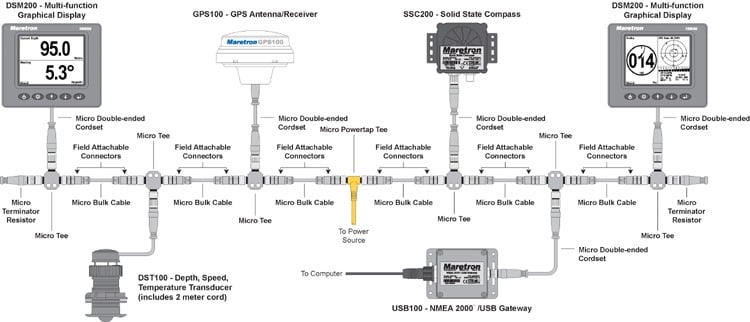
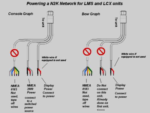
Pe (data wires), srpvc (power wires) construction: Use this diagram to connect the lvr to a lowrance gps unit that is not connected to a radar unit. You can connect power either at the end of your nmea 2000 network or in the middle.
The drain wire shields the signal, power, Ais or navtex receiver connected via nmea 0183 cable. Interface cables shall be kept as short as possible and shall not exceed 150 feet.
A quick guide to nmea 2000. Two signal wires, power and ground wires, and a drain wire. 27+ raymarine nmea 0183 wiring diagram.
Wiring diagram for lowrance nmea furthermore garmin new install no satellite signal also nmea wiring diagram for two screens. Check to see if an adapter cable exists (see the adapters page). The only directions that came with.
Actisense field fit connectors are available as straight or right angled options and in male and female variants to suit any installation requirement. Nmea2000 power tee, micro f/f, 8m 1 ea. One of the butt connectors will be used to connect the three bare wires.
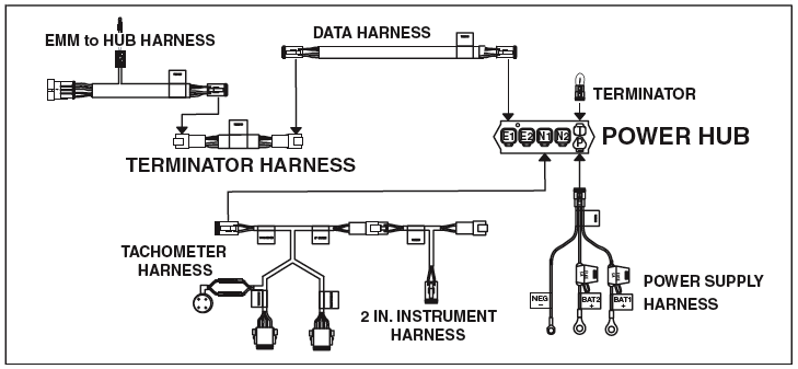
The lowrance nmea 2000 network starter kit includes everything you need to hook up your depth finder to your boat’s engine. A twisted pair employing 22 awg stranded wire shall be used for the nmea 0183 data signals. Search the brand and part number of.
These diagrams are for the use of professional installers. If you do not have a nmea 2000 network installed on your boat, you will need the appropriate nmea 2000 cables and connectors to build one. It reveals the parts of the circuit as simplified forms, as well as the power and signal connections in between the devices.
Nmea 2000 signals can be hampered by resistance, which increases with cable length, so keep the length for a single drop cable to less than 20 feet. Augmenting the power helps prevent an excessive drop in voltage. I think i got this diagram right, and i think it’s important to understand if your boat might end up with more than a few nmea 2000 powered devices on its network.as discussed on monday, the popular ‘light’ (or micro) size nmea cables only contain 22 awg power (and data) wires.its well insulated power wires are apparently perfectly safe (despite some internecine.
Before attempting to rewire a transducer connector you should: It’s possible to mix different forms of nmea 2000 cables, as this entry discusses, but regular seatalk and nmea 0183 are quite different in many ways. When planning where to place the.
Hs70 user manual hds units if you have an hds unit you must make a one time purchase of a nmea 2000 starter kit to create a nmea 2000 network.
Wiring in nmea 2000 system The Hull Truth Boating and

![]()
Nmea 2000 Wiring Diagram Free Wiring Diagram
Interfacing a SeaTalkng backbone to a third party NMEA

32 Lowrance Nmea 2000 Network Diagram Wiring Diagram List
NMEA 2000 YBW Forum
NMEA 2000 Drop Cable The Hull Truth Boating and


Nmea 2000 Wiring Diagram Free Wiring Diagram

[DIAGRAM] Garmin Gpsmap Nmea 2000 Wiring Diagram
Garmin Nmea 2000 Wiring Diagram Wiring Diagram

Lowrance Nmea 2000 Wiring Diagram
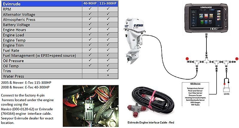
NMEA 2000 Evinrude Engine Interface Cable

Lowrance Nmea 2000 Wiring Diagram

Lowrance Nmea 2000 Network Diagram General Wiring Diagram
NMEA2000 Sample Rigging Prices for ETEC Moderated
Lowrance Nmea 2000 Network Diagram Free Diagram For Student
Lowrance Help Topics, Networking Diagrams, Troubleshooting
Building a NMEA 2000 Network off of new F200XB Page 2

How many wires are there in an NMEA 2000 cable?

Maretron NMEA 2000 Cable and Connectors