
Lutron 0 10v dimmer wiring diagram. Simply put, the control signal is a dc voltage that varies between zero and ten volts.
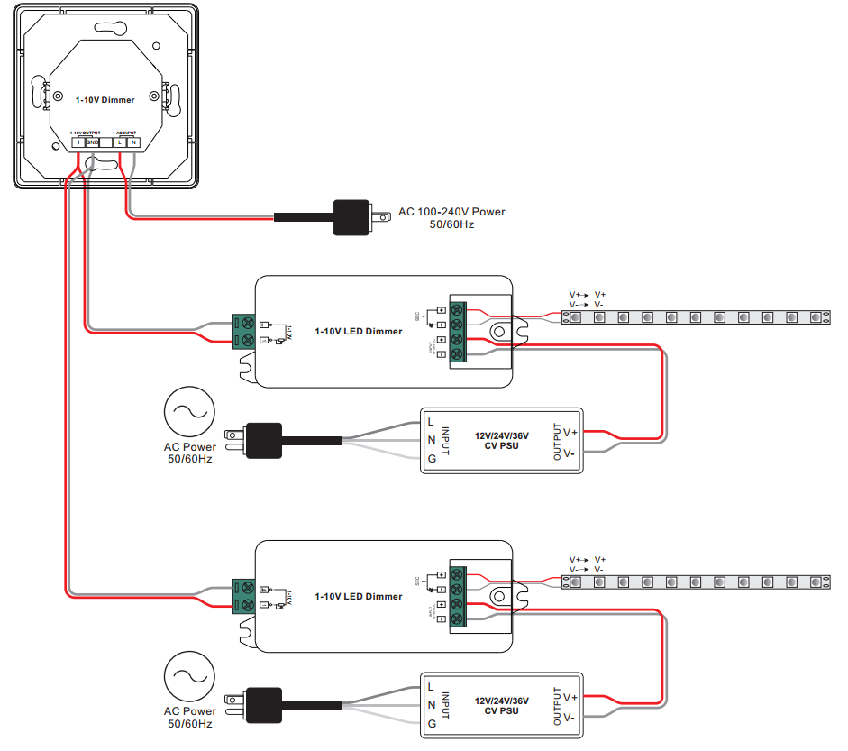
010V LED Dimmer module SLDDIM1B HUEDA™ LED
These wires are to be connected only to compatible dimming ballast/led drivers.
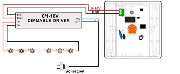
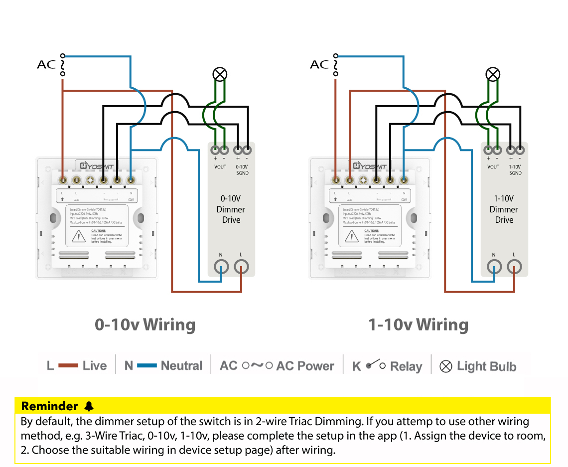
O 10v dimming wiring diagram. It is the default dimming driver provided with our warm glow dimming, color select and max output product lines, among others. 200 ma mechanical specifications wiring types: In many cases, the dimming range of the power supply or ballast is limited.
Do not touch or press leds against any surface as this can cause damage. It includes directions and diagrams for different varieties of wiring strategies as well as other products like lights, home windows, etc. When both wires are not touching, the dimming control output will be 10 volts, or 100%.
If installed as class 2, all devices in the circuit must be class 2 rated and this dimmer must be wired per instructions below. Work with power repeater to expand output unlimitedly. Ground wire to make a secure connection to the safety ground of the electrical the control4® v dimmer operates independently or as part of a control4.
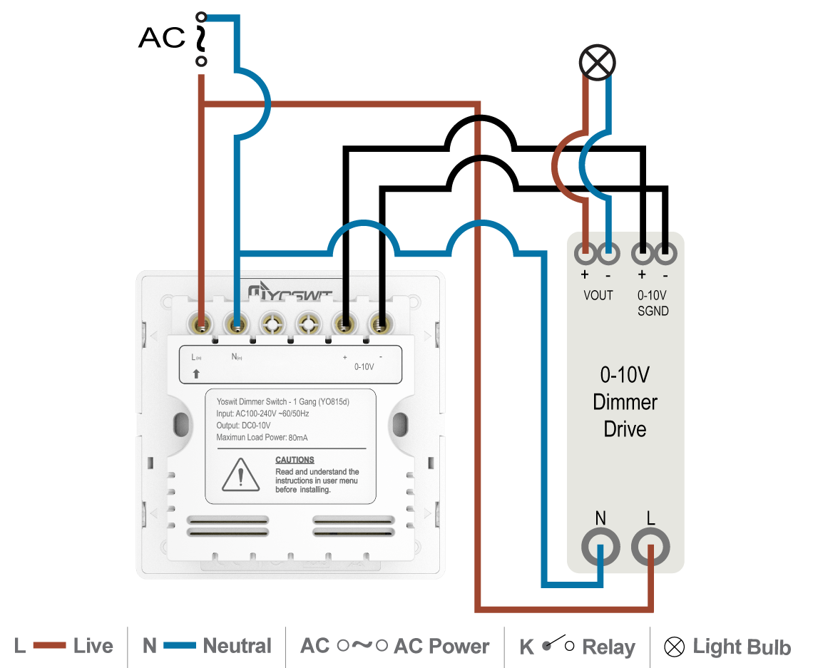
The dimming signal, which is connected to the source (driver) typically has a purple wire that represents +10 volts and a gray wire representing the signal. Depending on the information we had from adwords, maestro 0 10v dimming wiring diagram has very much search in google web engine. • most fixtures are sourcing and require a sinking control, per standards as specified by iec 60629.
| aurora, ohio 44202 | p: Wire the wall switch to the control device according to the instructions of the device and the appropriate wiring diagrams shown below. The dimming signal is usually connected to the lighting driver with a purple wire, which carries the 10 volt charge, and a grey wire, which is the common wire carrying the signal.
If the light output can only be dimmed from 100% down to 10%, there must be a switch or relay available to kill power to the system and turn the light completely off. Damaged leds may not light and can disrupt the flow of power. Determine how many lights will be run off of the switch.
Line.maestro 0 10v dimming wiring diagram (nov 29, ) ―. Www.moduled.io product specifications subject to change without notice. Wires on the wall switch are color coded.
Handle fixture with care to avoid possible. •power pack required for class 2 installations, for 347 v operation (canada), and for loads greater than 8. Lutron diva dvstv v dimmer for fluorescent and led the lutron diva dvstv is a v dimmer that easily lutron dvstv v installation instructions.
Wiring instructions 325 campus dr. Determine where you will run the wires and if any tools will be required to do taht.

0 10V Dimming Wiring Diagram Led Driver 12v 36w With 1

0 10 Volt Dimming Wiring Diagram
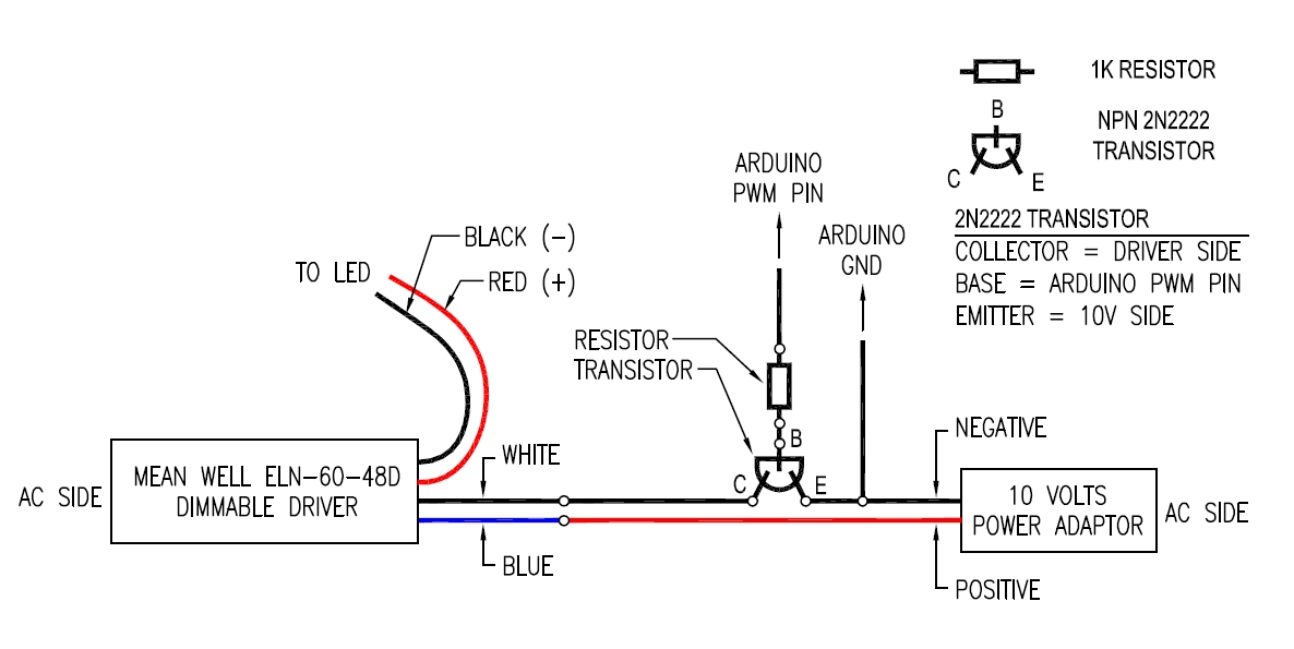
010v PWM dimming problem
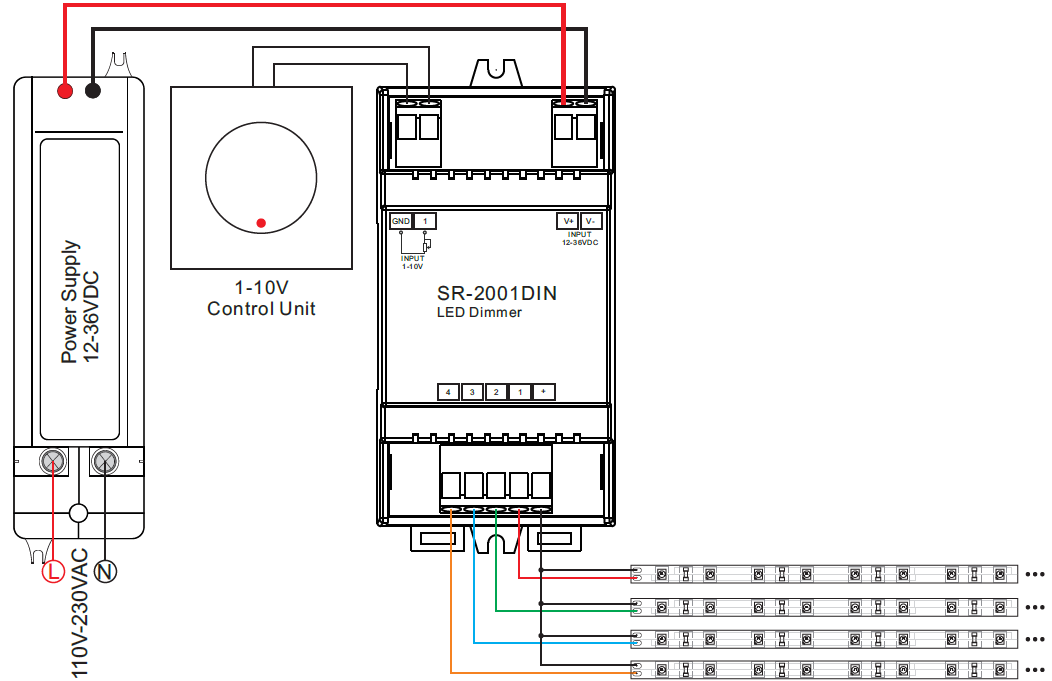
Din Rail Mounted 4 Channel 0/110V LED Dimmer SR2001DIN
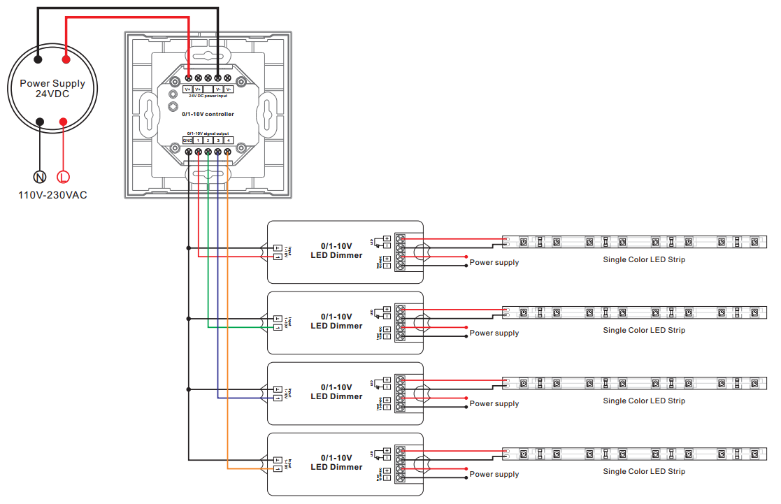
86*86 Size Knob Type LED Dimmer Switch For LED Lighting 0
32 0 10 Volt Dimming Wiring Diagram Wiring Diagram List
0 10 Volt Dimming Wiring Diagram Hanenhuusholli
31 0 10 Volt Dimming Wiring Diagram Worksheet Cloud
32 0 10 Volt Dimming Wiring Diagram Wiring Diagram Database
Smart Dimmer Switch Socket 86 Smart Home
AC Input 110V Rotary Dimmer SR2202N110V
110V Dimmable LED Driver (Constant Current) White 15W


19 Fresh Occupancy Sensor Wiring Diagram
Wiring Diagram 1 0 10 Volt Dimming Wiring Diagram

Lutron 0 10v Dimmer Wiring Diagram
eCoveLine XL 010V by Solid State Luminaires

010vdimmingsystem MOONS' SPARK
32 0 10 Volt Dimming Wiring Diagram Wiring Diagram List

0 10v Dimming Wiring Diagram Atkinsjewelry
