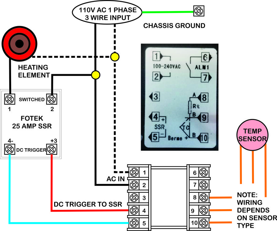
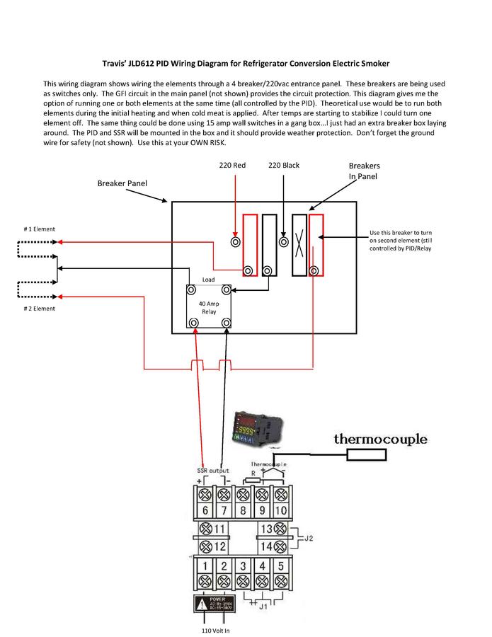
A wiring diagram is a simplified standard photographic representation of an electric circuit. This and other related handbooks can also be downloaded from www.eurotherm.co.uk.

Temperature Controller Wiring Diagram / Pid Temperature
After that, fix the temperature controller with attached two bolts of the fixer under torque of 0.29n to 0.39n.

Pid temperature controller wiring diagram. Its submitted by management in the best field. Imho, you should get a rotary switch that controls the ssr control signal from the pid.that way the pid would switch either one, two, three, or none of the ssr's. It shows the components of the circuit as simplified shapes, and the skill and signal contacts in the midst of the devices.
The pid has 12 numbered screw terminals and the silver label diagram shows where the ssr and the thermocouple (tc) are wired to these. Start date dec 22, 2010; 7 & 8 and rtd3 to terminal no.
Here are a number of highest rated pid controller wiring diagram pictures upon internet. If you know how to translate it, wiring everything up is quite simple. Let's start with the temperature sensor.
We identified it from trustworthy source. Embedded pid temperature control, part 1: All line voltage output circuits must have a common disconnect and be connected to the same pole of the disconnect.
For a temperature between 68° and 67°, the controller takes no action and the heater remains off. Short terminals 8 & 9. And output wiring for current 14 vdc is rated class 2.
Size your wires and breakers according to amperage (of course).the pid output signal should be no different.but you need to route it differently. K, e, s, r, j, t, b, wre3/25 rtd(resistance temperature detector): It reveals the components of the circuit as streamlined shapes, and the power and also signal connections in between the devices.
A wiring diagram typically gives. Mypin ta4 snr controller for uds. 3.2 make sure the surrounding temperature is within the stipulated temperature range, especially when there are two or more temperature controllers.
2 shows circuit diagram of the digital temperature controller. Pid temperature controller wiring diagram. Simple solar charge controller circuit diagram.
Hopefully my digram below will make things a little clearer. Rosemount temperature transmitter wiring diagram. Specification input type thermocouple (tc):
However, it's not instantly clear what to do with the ssr and how and where to power everything. Salt dogg spreader controller wiring diagram. Collection of pid temperature controller wiring diagram.
To get book file pdf td4 snr ssr controller wiring diagram. This chapter takes you through step by step instructions to help you to install, wire, configure and use the controller. Once the temperature reaches 68°, the heater shuts off.
Pid temperature controller wiring diagram. Control wiring as show below: Pt100, cu50 input range see table 2 display dual lines, four digits, °f or °c
Posts related to pid temperature controller wiring diagram. Mishimoto fan controller wiring diagram. Connect pt100 between terminal no.
Pid temperature controller ecorenovator kualitas premium digital temperature controller pid td4 snr ssr controller wiring diagram worksheet and wiring 28 circuit diagram of pid controller pid schematic 28 circuit diagram of pid controller pid. The controller would then send a signal to increase the applied heat to raise the temperature back to the setpoint of 68°. By ahmad jamaluddin january 06, 2020 post a comment.
16 awg or larger wires rated for at least 75˚ c. The mypin ta4 is a pid temperature control device similar to the here is the pin out schematic for the wiring of the screw terminals on the.jun 09, · all of the wiring diagrams i've seen for v are wired similar to this, they just include. In the instruction manual for your pid and, possibly on a sticker on the case, will be a wiring diagram like the one above.
For supply connections use no. We resign yourself to this kind of pid controller wiring diagram graphic could possibly be the most trending topic bearing in mind we part it in google gain or facebook. Input wiring for thermocouple, current, and rtd;
Typical wiring diagram for PID temperature controller
Pid Temperature Controller Wiring Diagram Diagram For You
Watlow 96 Rancilio Silvia Brew and Steam PID Control
Temperature controller Smoking Meat Forums The Best

Pid Temperature Controller Wiring Diagram Diy Stc 1000 2

Pid Temperature Controller Wiring Diagram / How To Control

Pid Temperature Controller Wiring Diagram Free Wiring
Build your own digital forced draft smoker controller UK
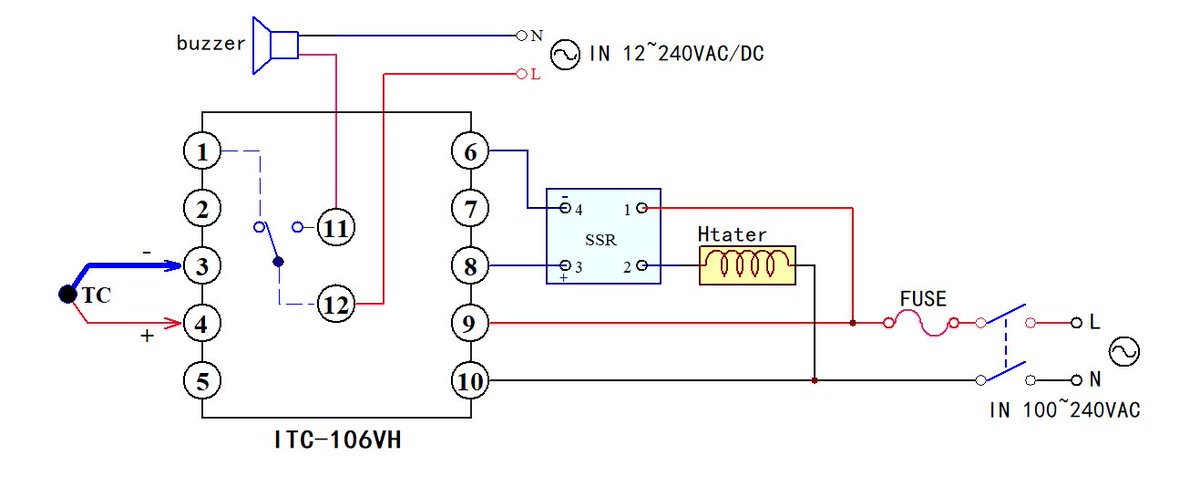
Pid Temperature Controller Wiring Diagram General Wiring
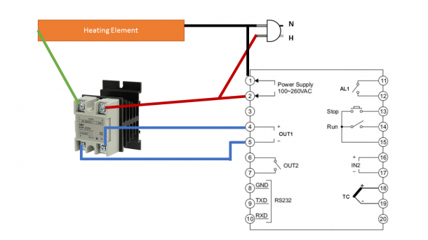
Pid Temperature Controller Wiring Diagram
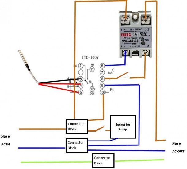
Pid Temperature Controller Wiring Diagram
Mechanical Timer Switch Wiring Diagram Apartment Home Decor
PID Controller Wiring Diagram Photo by boolits Photobucket

Pid Temperature Controller Wiring Diagram PID

120V Thermostat Wiring Diagram Nice Pid, Wiring To
Wiring Diagram for JLD 612 PID Temperature Control

[YW_7045] Pid Wiring Diagram With Heat Sink Wiring Diagram

Pid Temperature Controller Wiring Diagram Pid Controller


