1 heat / 1 cool thermostat. 32 honeywell gas valve wiring diagram.
Furnace Thermostat Wiring and Troubleshooting HVAC How To
Thermocouples have a maximum output of 25 to 30 millivolts millivolt reading for thermocouple pilot on:
Thermopile wiring diagram. Wiring the ir thermal amg88 grid eye thermopile infrared array sensor. Thermopile gas valve wiring diagram doc download. *if higher than 35mv check connections and switch.
(to din 47100) white, brown. In the united states, when you’re connecting thermocouple wires to instrumentation, red is always negative. Well, cd will make you closer to what you are willing.
041a5034 safety sensor kit parts liftmaster. There are lots to handle with this device and it can be quite difficult. Ensure you wire it exactly as shown in the diagram above.
Thermocouples are simple temperature sensors consisting of two wires made from dissimilar alloys. The 4 pin m12 plug standard is broken down as follows. Here are some basic wiring diagrams from the reference section of the lesman catalog with rules to follow and some suggestions on specifying the right thermocouple wire.
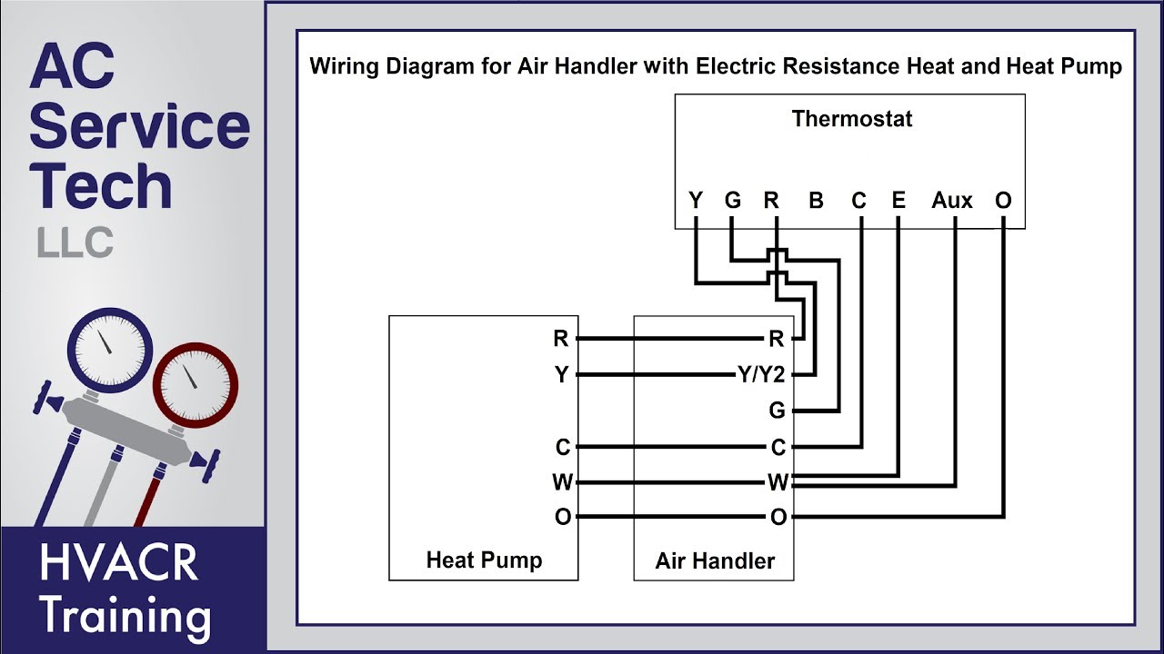
Heat pumps are different than air conditioners because a heat pump uses the process of refrigeration to heat and cool.while an air conditioner uses the process of refrigeration to only cool, the central air conditioner will usually be paired with a gas furnace, an electric furnace, or some other. The intent of this paper is to present and explain how to use thermocouples and how to design thermocouple. How to wire multiple thermocouples to a single instrument through a switch as you can see, none of the diagrams are really complicated, but there are some rules you need to follow to do it properly.
Wiring for input 2 is the same as that for input 1. You may not forcedly to always finish higher than reading a cd in brusque time. Official post from ac service tech.
We use cookies to improve your experience using this site. It will be lonely subsequently you have spare period and spending few period to. Gas fireplace wiring diagram wiring diagram is a simplified up to standard pictorial representation of an electrical circuit.
Voltage drop across the switch terminals burner on: The diagram shows 120v coming into a 120v24v transformer and. These devices are simple in construction and easy to use.
Set meter to mv or volts dc place one lead to tp/th and place one lead to th Colors, terminals, functions, voltage path! Can be mounted in any position except upside down.
Honeywell millivolt gas valve wiring diagram for your needs. Heat pump thermostat wiring explained! This is a polarity sensitive system.
Millivolt fryer wiring diagrams robertshaw 700 720 series two stage 4 5 recommended spare a nest thermostat to gas fireplace systems installing on system electronic ignition ipi fireplaces models nmv 2 pmv infra 750 mv thermopile 35 obsolete vs8510 vs8520 hearthstone modena stove millivolt fryer wiring diagrams robertshaw 700 720 series two. The following wiring diagrams are for illustration purpose only. The thermocouple diagram below are showing devices for the measurement of emf in.
It looks as if you get a floating 1.2v supply between terminals 3 and 4, with terminal 3 positive. 750 millivolt gas valve, thermopile wiring & wiring diagram! A thermocouple consists of two metal wires or legs and they jointed at one end to create a junction.
A wiring diagram is a simplified standard photographic representation of an electrical circuit. One valve controls gas flow to the pilot in a typical gas fireplace valve the pilot runs on 30mv ( millivolts ) and the burner runs on 500 mv. Omron photo eye wiring diagram.
Wiring diagram for connecting the lamp to radios. 8 to 30 mv set meter to mv or volts dc place one lead to wire (supplied) place one lead to outer casing if the millivolt reading is less then 7 mv then change the thermocouple shutdown time for thermocouple after flame failure is up to 90 sec. But, like any electronic component, they require a certain amount of explanation.
Honeywell millivolt gas valve wiring. This includes a wiring diagram. This [rtf] thermopile gas valve wiring diagram will be always good pal any time.
I show you how to light the pil. If you should be happy with some pictures we provide please. Cynergy3 ittu programmable temperature probes rhopoint components.
Thermopile wires must also be located with red at th/tp and white at tp on the gas valve. Installation instructions gas conversion procedures see gas valve illustration below and gas valve, burner and orifice location on page when performing the following conversions. The types s, r, and b are considered noble metal thermocouples.
This is how to wire the thermopile to the 750mv gas valve for the pilot and main gas burners. When that junction experiences a variation in temperature it produces an electric voltage. 750 mv thermopile and gas valve.
Standard thermocouple duplex difference between 2 wire rtd 3 grounding thermopile pt100 colour codes iec 60751 temperature sensor instruction manual atex approved sensors with how work thermocouples quick connector plug measurement downhole geo psi real t type omega the. Millivolt gas valve wiring diagram fan hot (black) fan netural (white) electronic fan speed control hi mh ml lo off fan speed test fan turns on to. Generally, thermocouples are designed in.
Here we learn for the first time that there were actually three output voltages; The thermopile, energized by the pilot flame, generates sufficient power to operate the gas valve and on/off switch.

Thermostat wiring question (HVAC has 7 wires) Ask the

Honeywell Manual thermostat Wiring Diagram Sample
Honeywell Thermostat Wiring Diagram 3 Wire Cadician's Blog
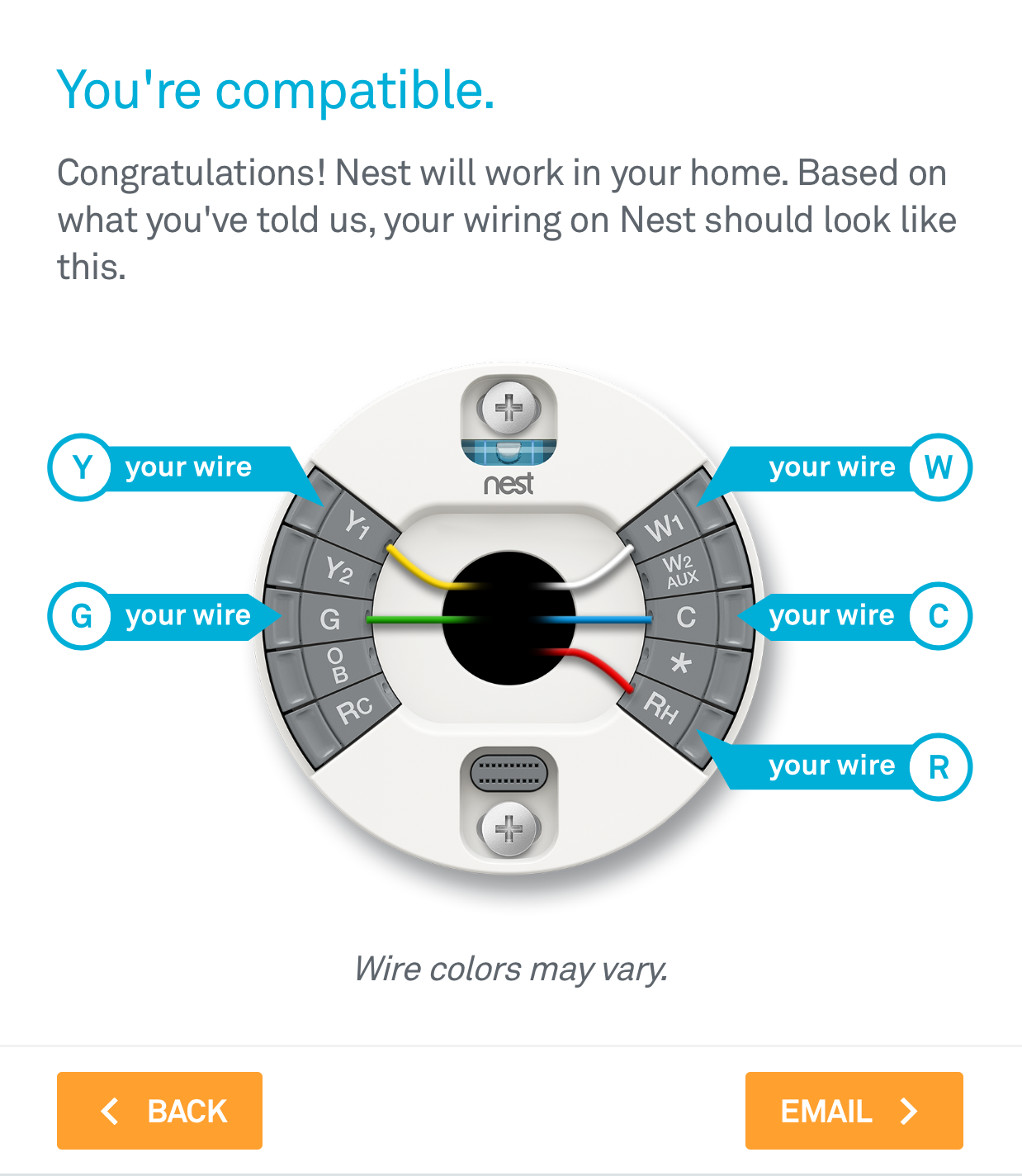
How To Install The Nest Thermostat The Craftsman Blog

Duo Therm Thermostat Wiring Diagram Wiring Diagram And

Collection Of Heating and Cooling thermostat Wiring
Honeywell Ct87n4450 Thermostat Wiring Diagram
5 Wire Thermostat Wiring Diagram Wiring Diagram
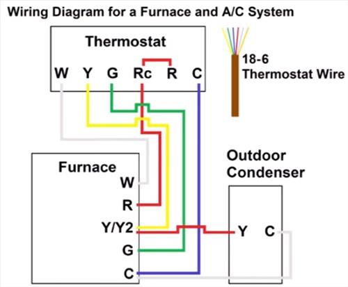
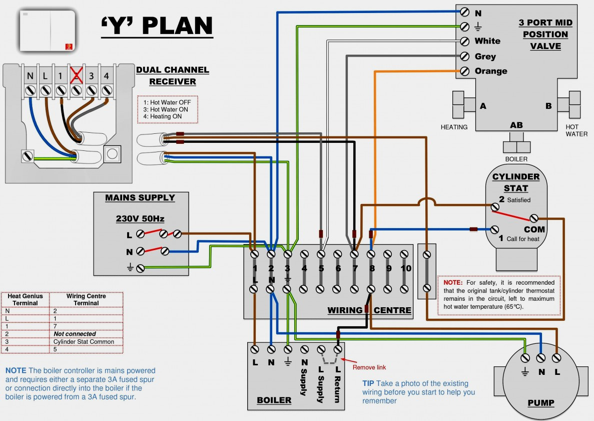
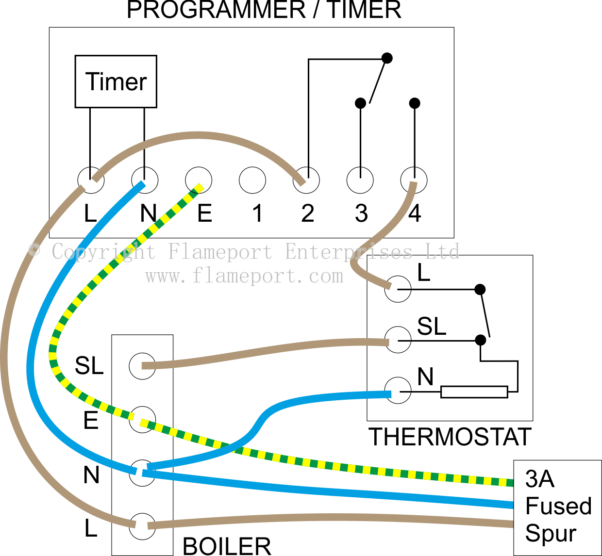
Room thermostat wiring diagrams for HVAC systems
4 Wire Thermostat Wiring Diagram Heat Only For Your Needs
Thermostat Wiring Diagrams! 10 Most Common! YouTube

Thermostat Wiring Diagram Rth2510

Wiring Diagram for thermostat to Furnace Collection

Get Wiring Diagram for A Nest thermostat Download

Honeywell thermostat Ct87n Wiring Diagram Free Wiring

Dometic Capacitive touch thermostat Wiring Diagram Sample
Guide to wiring connections for room thermostats

Honeywell Manual thermostat Wiring Diagram Sample
Thermostat Wiring Explained
