
Dexter nev r adjust 12 25 x 3 375 electric trailer brake right hand passenger s side 9k 10k lbs axle capacity drum brakes products. Trailer brake wiring problem forest river forums.
Dexter Trailer Brakes Wiring Diagram Trailer Wiring Diagram
Auxiliary connection is optional, it may be connected to any 12v to 24v constant power source or left unconnected.

Dexter electric brakes wiring diagram. By vallery masson on may 25, 2021 may 25, 2021 leave a comment on dexter electric brakes wiring diagram dexter axle offers a state of the art inertial controller called the predator dx. It is dexter's recommendation that a common ground be run from the trailer plug to the magnets. It represents the power circuits factors as simple forms, using the real power and terrain contacts between the two as colored circles.
Fill the unit with dot 3 or dot 4 brake fluid to the bottom of the Breakaway switch switches battery power to brakes if Proper electrical wiring is critical for performance of any brakerite system.
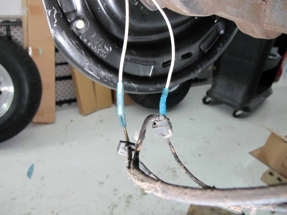
The white wire is the supply wire, the black wire is the dexter wire that crosses over to the right side brake: Circuit clearance & tail lights stop & lh turn ground auxiliary. We do have a wiring diagram for you!
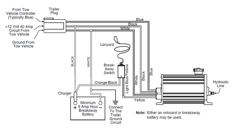
Brake line must be compatible with dot 3 & dot 4 brake fluid. Dexter sway control wiring electric brake (blue wire) connections the tow vehicle brake controller signal (blue) wire must be securely connected to the dsc brake signal (blue) wire as well as to the “cold” wire from the breakaway switch as shown in the wiring diagram. This controller features a patented accelerometer design which senses the deceleration of the towing vehicle and sends a proportional voltage to the electric trailer brakes.
Electric trailer brake wiring diagram. Also note that the brakes should be wired in parallel, not in series. Wiring diagram for utility trailer with electric brakes.
Connect the brake line from the trailer brakes to the 3/ 16 inverted flare fitting on the actuator. Break away systems may be added to the service brake circuit. Connect the brake line from the trailer brakes to the ³⁄₁₆ inverted flare fitting on the actuator.
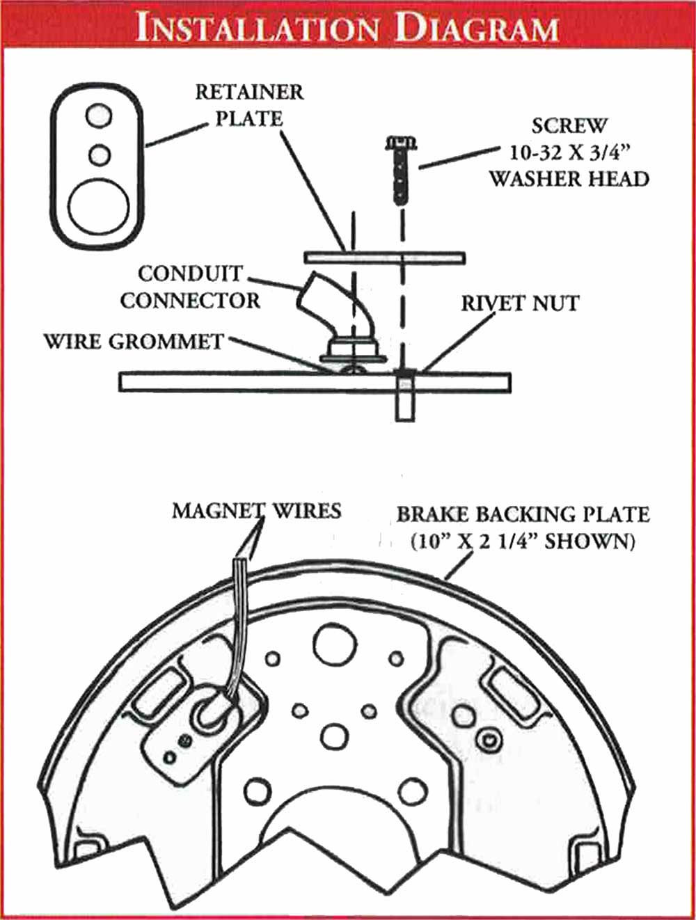
Do not ground each brake individually to the trailer frame or structure. Use one wire to connect to power from the brake controller and use the other to attach to the ground. Dexter electric brakes wired in parallel.
(always ground trailer brakes through connector). Electric brake terminal #2 blue electric brake ground terminal #1 white double filament bulb brown yellow white green red black orange brown blue grey #3 to tail running & license lights #5 stop & left turn #4 battery charge #7 aux. This dexter trailer brakes wiring diagram version is far more appropriate for sophisticated trailers and rvs.
I do not know what size main wire runs inside the hull, but in the left wheel well there are two pairs of 18 awg wires, one for each axle. Just let me know if you have any additional questions regarding the installation. Dexter trailer brakes wiring diagram wiring diagram is a simplified good enough pictorial representation of an electrical circuit it shows the components of the circuit as.
Dexter trailer brakes wiring diagram wiring diagram is a simplified good enough pictorial representation of an electrical circuit it shows the components of the circuit as simplified shapes and the capability and signal connections amongst the devices. Vehicle to be moving in order for the dexter e/h brake. The black wire will connect to the 12v circuit coming from the vehicle's trailer wiring that is always hot.
Electric brake controller wiring diagram. Trailer wiring diagram lights brakes routing wires connectors. Flush existing brake system and lines with dot 3 or dot 4 brake fluid prior to connecting to the dexter e/h unit.
I have attached a wiring diagram and review videos for you to check out. Connector used to connect and disconnect trailer and tow vehicle. Circuit #6 stop & right turn #2 electric brake #8 aux.
Use a 4mm x 2 core cable for your active and earth wires to the brakes separate from wiring used for lighting etc. Brake line must be compatible with dot 3 & dot 4 brake fluid. Dexter electric brakes wiring diagram.
Controller electric brake controller provides power to the magnets to actuate the trailer brakes. Flush existing brake system and lines with dot 3 or dot 4 brake fluid prior to connecting to the dexter e/h unit. The dexter wires are a connected pair of 20 awg wires, running through the hollow axle tubes.
Titan brakes & actuators by dexter & ufp by dexter 1041 baxter lane, winchester, tn 37398, usa. It represents the power circuits factors as simple forms, using the real power and terrain contacts between…

Dexter® Electric Trailer Brakes Right (Curb Side)
Dexter Trailer Brakes Wiring Diagram Wiring Diagram

Dexter Trailer Brakes Wiring Diagram Trailer Wiring Diagram

Dexter Hydraulic Brake Actuator Wiring Diagram
Dexter Trailer Brakes Wiring Diagram Wiring Diagram

Dexter Trailer Brakes Wiring Diagram Wiring Diagram

Dexter Trailer Brakes Wiring Diagram Trailer Wiring Diagram
Dexter Trailer Brakes Wiring Diagram Wiring Diagram
Dexter Electric Over Hydraulic Brake Actuator 1,600 psi

46 Dexter Trailer Brake Wiring Diagram Wiring Diagram

trailer breakaway switch wiring diagram Wiring Diagram
Dexter Trailer Brakes Wiring Diagram Wiring Diagram


Dexter Trailer Brakes Wiring Diagram Trailer Wiring Diagram

Dexter Trailer Brakes Wiring Diagram Trailer Wiring Diagram

Dexter Electric Brakes Wiring Diagram easywiring
Dexter Trailer Brakes Wiring Diagram Wiring Diagram

Trailer Break Wiring

Trailer Brake Diagram Dexter Trailer Brakes Wiring
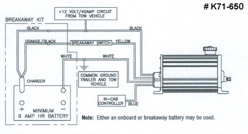
Wiring the Breakaway Switch to Dexter Electric Over