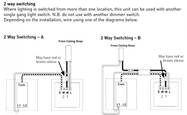
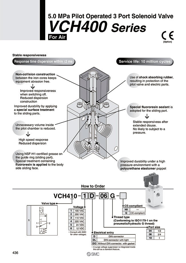
Here are some details of hydraulic pump electric diagram,12vdc hydraulic power unit and 24vdc hydraulic power pack hydraulic circuit diagram and electrical diagram. Solenoid isarmatic hydraulics wiring diagram for western plow.

Hydraulic solenoid Valve Wiring Diagram Download
These diagrams show the internal components of the solenoids.

Hydraulic solenoid wiring diagram. May 04, 2010, 03:48:59 pm ». How to wire hydraulic power pack,power unit diagram design for 12 volt hydraulic pump wiring diagram by admin. Theres not relays but there is dioades (sp?).
12v dc electric motor drives a hydraulic pump that moves fluid through a.ford sport trac with multi coil system , spark plug wire set by beck arnley®. Typically a process flow schematic drawing will provide basic levels of technical information to highlight basic essential flow control and flow paths. With such an illustrative manual, you will be capable of troubleshoot, avoid, and total your projects without difficulty.
These are the solenoid coil terminals. If your just running the up and down or neutral return switch that comes with bennett pump then it wires directly to the switch. The full manual book is here.
It is really simple to draw a wiring diagram. Refer to the wiring diagram for the specific model. Hydraulic solenoid valve wiring diagram from i.ytimg.com.
Solenoid lsarmatjc mark ila hydraulic system parts diagram. Block diagram of power to hydraulic pump. Put the 24v in one way, and a will activate.
Isarmatic® mark iiia hydraulic systems. The lippert hydraulic slideout and hlg system is an electric/hydraulic system. John deere 318d, 320d skid steer loader (manual controls) workshop diagnosis & test service manual includes:
Hydraulic solenoid valve wiring diagram. The diagram below shows a standard hydraulic wiring schematic. Wiring diagram/instructions for hydraulic diverter.
And i went through almost a. 1 start by connecting the ground clamp of your test light to the negative battery post and touch the point to the positive post to make sure the test light lights up. When the piston is fully retracted and hydraulic pressure builds, the unloader (relief) valve will lift and maintain the system’s pressure at setpoint.
3 when you push the up or down button while touching the. Otherwise, the structure won’t work as it should be. * numbered table of contents.
Mechanic's guide right and ensure that your western plow warranty is maintained. This allows hydraulic fluid to enter the top chamber of the piston and drive it down. 12 volt solenoid wiring diagram 5 connection wiring diagram center.
And through the electrical schematic. 2 now touch the test light to the dump trailer solenoid positive battery cable light should be. Black wire from hard wired controller b.
Designed utilizing the latest technology, this product by beck arnley. An engineering line diagram of p and id will show more detailed and precise information. The solenoid is controlled by the direction current goes through no1.
A single trick that i actually use is to print the same wiring diagram off twice. Figure 12 shows a wiring diagram for a power saver. I purchased this plow and truck during the summer in which the all i could read was solenoid isomatic.
Strip 20mm off each of the individual wires. The pump system is a isarmatic® hydraulic system. Wiring a 3 wire solenoid valve to the w100 controller.
Warn solenoid wiring diagram reading industrial wiring | pdf. Solenoid isarmatic hydraulics wiring diagram for western plow. When you make use of your finger or stick to the circuit together with your eyes, it is easy to mistrace the circuit.
17052019 17052019 5 comments on solenoid isarmatic hydraulics wiring diagram for western plow i purchased this plow and truck during the summer in which the all i could read was solenoid isomatic. Each part ought to be set and linked to other parts in particular manner. Ground is connected to earth ground, and is not used at all to control the solenoid.
Process equipment details and drawings relate to the type of schematic drawing provided. And more, a wireless remote connect wire drawing also show below for single acting hydraulic power pack.this wireless remote can be with a quick connector ,can be changed with our standard 2 buttons. Complete diagnosis & test manual with electrical wiring diagrams for john deere 318d and 320d skid steer loader (manual controls), with all the shop information to maintain, diagnose, and service like professional mechanics.
Diagram chevy western snow plow wiring full version hd quality. 12 volt hydraulic pump wiring diagram throughout 12 volt hydraulic pump wiring diagram by admin. Put 24v in reverse (swap wires to no1 and no2 termnals), and b activates.
Print the cabling diagram off plus use highlighters to be able to trace the circuit. Xv2 vehicle side harness snow plow parts list fisher. Solenoid swap the largest community for snow plowing and ice management professionals find discussions on.
Solenoid Valve Wiring Diagram Complete Wiring Schemas

Smc solenoid Valve Wiring Diagram Free Wiring Diagram
Hydraulic Solenoid Wiring Diagram Wiring Diagram

Hydraulic Solenoid Wiring Diagram

Hydraulic solenoid Valve Wiring Diagram Download

Hydraulic Solenoid Valve Wiring Diagram Wiring Diagram

Hydraulic solenoid Valve Wiring Diagram Download

Asco Redhat 2 Wiring Diagram Free Wiring Diagram

Monarch Hydraulic Pump Wiring Diagram

Hydraulic solenoid Valve Wiring Diagram Sample

Hydraulic Solenoid Valve Wiring Diagram Wiring Diagram

Hydraulic Solenoid Valve Wiring Diagram Wiring Diagram

Hydraulic Solenoid Valve Wiring Diagram Wiring Diagram

Hydraulic solenoid Valve Wiring Diagram Free Wiring Diagram

Hydraulic solenoid Valve Wiring Diagram Download

Wiring Diagram PDF 12 Volt Hydraulic Solenoid Valve

Hydraulic solenoid Valve Wiring Diagram Download

Smc solenoid Valve Wiring Diagram Collection Wiring
33 Hydraulic Solenoid Valve Wiring Diagram Wiring


