Air handlers (fan coil units). Connecting thermostat wiring use “table 1.
Touch lever back and insert wire through hole located on bottom side of connector.
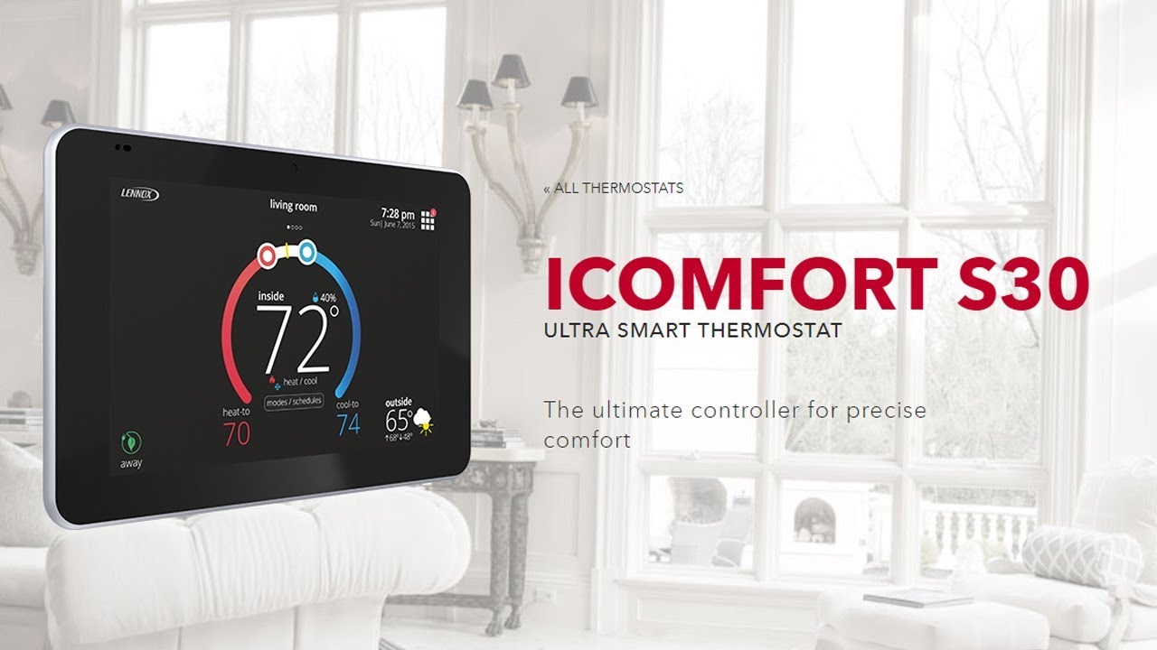
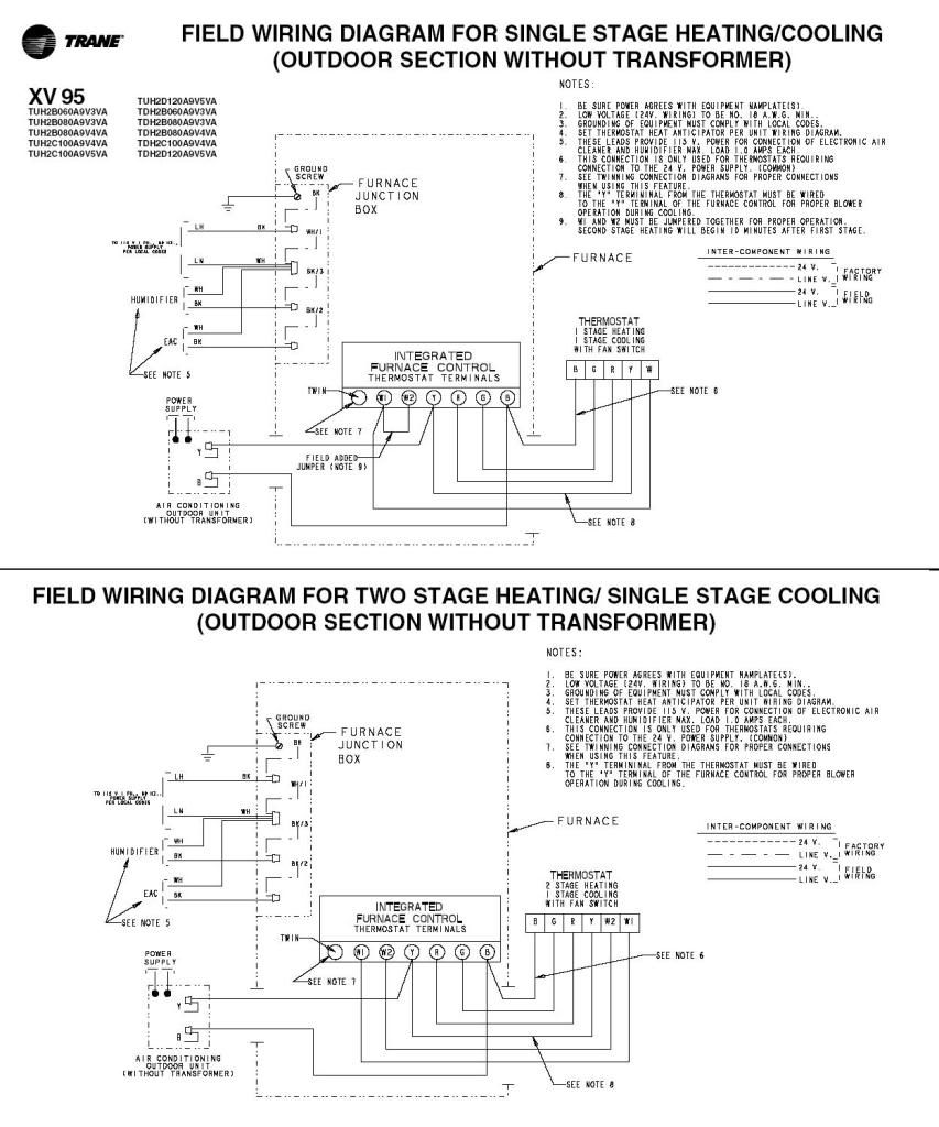
Lennox icomfort wiring diagram. D the lennox icomfort touch™ thermostat must be used in communicating page figure cbx32mv air handler unit typical wiring diagram. If you look at the bottom edge of your air handler's control board, there is a terminal block to the right of the two comfortsync connections that has been labeled with conventional thermostat signal labels. Refer to lennox equipment limited warranty certificate included with unit for the thermostat and damper field wiring.
Need wiring diagram for lennox 84w88 installation. I need to connect a humidifier to my sl280uhv furnace and icomfort wifi thermostat. Thermostat wire termination in icomfort® system
Release lever to secure wire. Complete icomfort systems — air handler and heat pump unit. Using wiring diagrams provided starting with figure 3 on page 7.
Lennox hvac systems lennox® comfort is made even better with the. I show the low voltage thermostat wiring diagrams for heat pumps, electric strip heating, furnaces, air conditioners, boilers, and 750mv gas valves. Make sure that all wiring conforms to local and national building and electrical codes and ordinances.
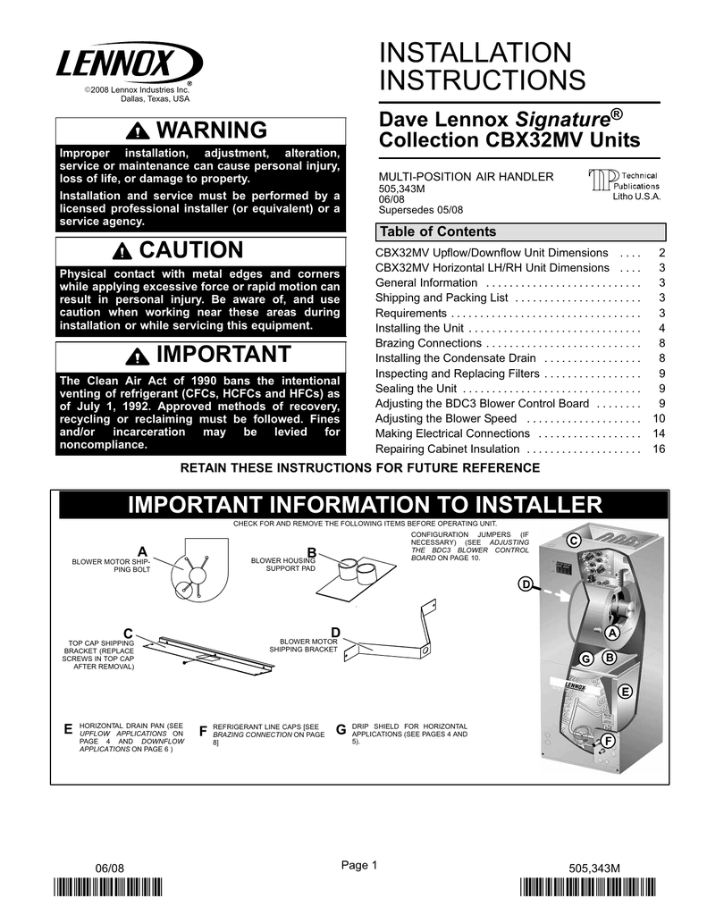
But lennox manual say one wire to terminal c and the. 43 partial icomfort system — icomfort furnace and lennox (wiring diagrams are also shown beginning on page 59 of this manual.) note − if electric heat strips are used with an icomfort −enabled air handler, the strips must be configured on the air handler control (ahc) board before beginning the discovery sequence below.
I am installing an aprilaire 700, and the wiring diagram is for a standard rcywg thermostat connection. I am replacing a lennox icomfort 10f81 thermostat with a nest learning thermostat. Connect the outdoor sensor (if used) to the t connections on the thermostat (wire run should not exceed 300' [100m]).
If this is a replacement thermostat, connect This means that your control board. Icomfort® communicating thermostat (zone 1 master).
System is a lennox heat pump with outdoor compresor/condensing unit part no. A lennox communicating thermostat must be used in communicating applications. Release lever to secure wire.
You should be able to wire your thermostat to the conventional terminal block on the air handler. A single wire should then be connected to the indoor unit end of the wire bundle and attached to the “c” terminals as shown in the dia gram above. Service manuals for lennox commercial light commercial hvac equipment.
Wiring diagram for lennex m30 thermostat. Lennox parts ready to ship looking for lennox g16 furnace manual blower motor or lennox g16 wiring diagram part list?. Seal the hole in the wall with a suitable material to prevent drafts from entering the thermostat case.
Hello, i am installing an aprilaire 700m, and the wiring diagram is for a standard rcywg thermostat connection. I am looking for a wiring diagram for connecting a honeywell he360a humidifier to a carrier 58mvp furnace. Hpp, serial no e.lennox icomfort m30 installation and setup manual pdf download.lennox icomfort e30 installation and setup manual pdf download.
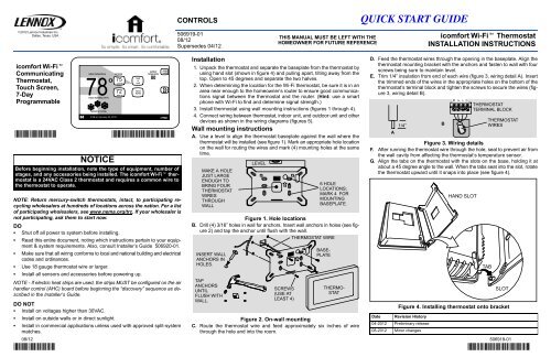
Cabinet configuration without a manual, installer can also run. Xc25 installation and service procedure. Dallas, texas, usa icomfort wi‐fi® thermostat icomfort wi‐fi® web and mobile apps this manual must be left with the homeowner for future reference icomfort® units the icomfort wi‐fi® thermostat works with the following indoor and outdoor units:
After all wiring connections are made, apply power to the system. 43 partial icomfort system — icomfort furnace and lennox conventional air conditioner. End of each control wire.
Solving simple problems related to programmable lennox thermostats, such as lennox's elite series, can maximize energy efficiency and performance. 18 #awg thermostat wire make connections to the smart hub using included wiring diagrams in this instruction. Discussion starter · #1 · mar 8, 2014.
Wiring diagram in the installation instructions for additional information about extended dampers,. Connect wiring between thermostat, indoor unit, and outdoor unit as shown in the appropriate wiring diagram. Terminal designations” on page 7 for connecting the thermostat wiring to the back plate terminals.
Use wire nuts to bundle the unused wires at each end of the cable. We use cookies to give you the best possible experience on our website.
Wiring Diagram For Lennex M30 Thermostat
I have a Lennox furnace (EL296UH070XV36B05) that is

Wiring Diagram For Lennox M30 Thermostat

Wiring Diagram For Lennex M30 Thermostat

Lennox Thermostat Wiring Diagram Wiring Diagram
Lennox Humidity Sensor Wiring Diagram Wiring Diagram Schemas

Lennox Xp21 Nest Wiring Diagram Nest Wiring Diagram

Lennox Thermostat Wiring Diagram Wiring Diagram

Wiring Diagram For Lennox M30 Thermostat
Lennox 81m27 Thermostat Wiring Diagram Wiring Diagram

Lennox Furnace Thermostat Wiring Diagram Diagram Lennox

Aprilaire 700 W/ Lennox Tstat HVAC DIY
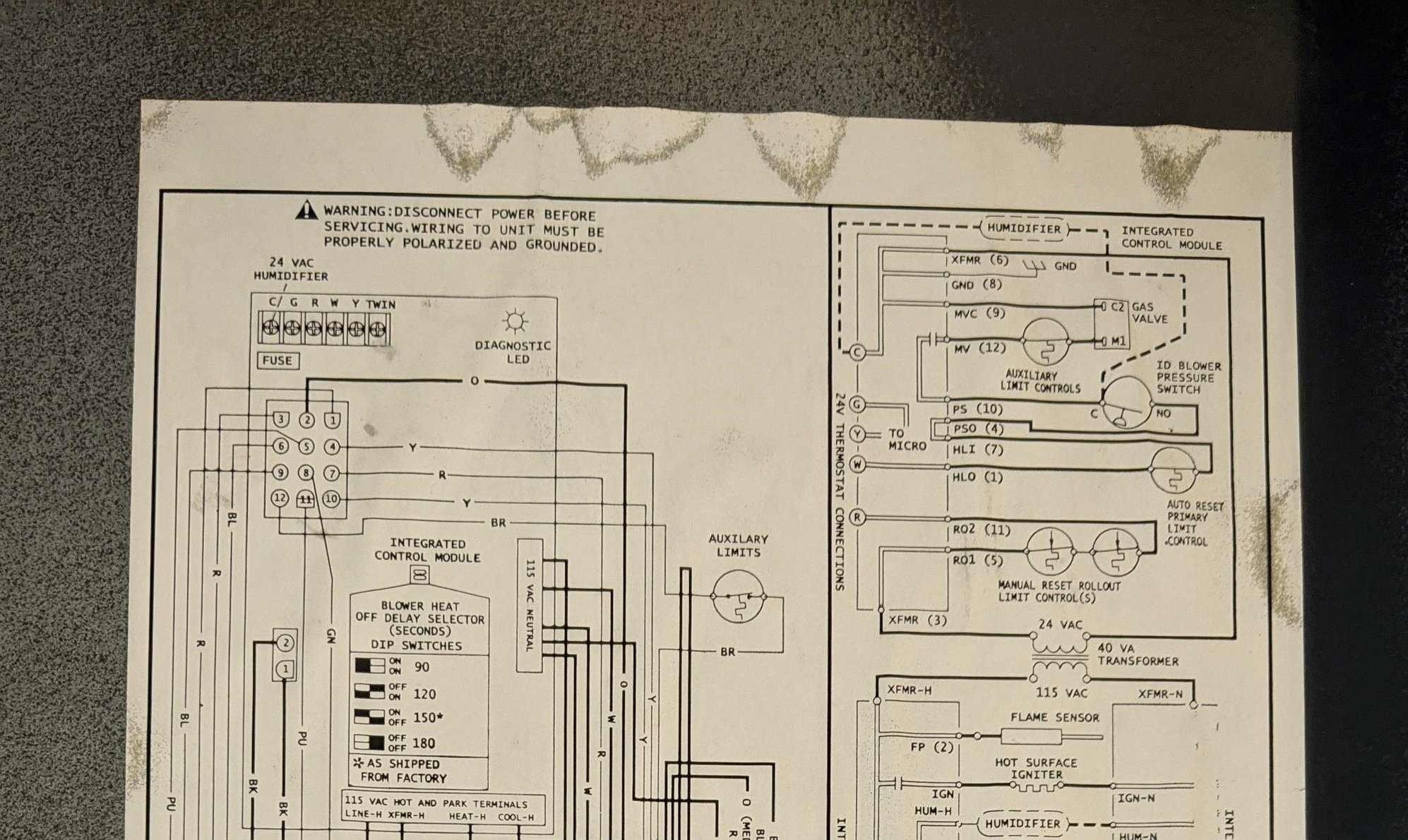
Aprilaire 700 w/ Lennox SLP98 & TStat

Lennox 5500 Thermostat Manual 9 Images Honeywell Th2110d

Lennox Y2081 Wiring Diagram 2 The wiring diagram on

Lennox Thermostat Wiring Diagram Wiring Diagram
ecobee with variable speed furnace Lennox

Lennox 5500 Thermostat Manual 9 Images Honeywell Th2110d

Lennox Thermostat Wiring Diagram flilpfloppinthrough

