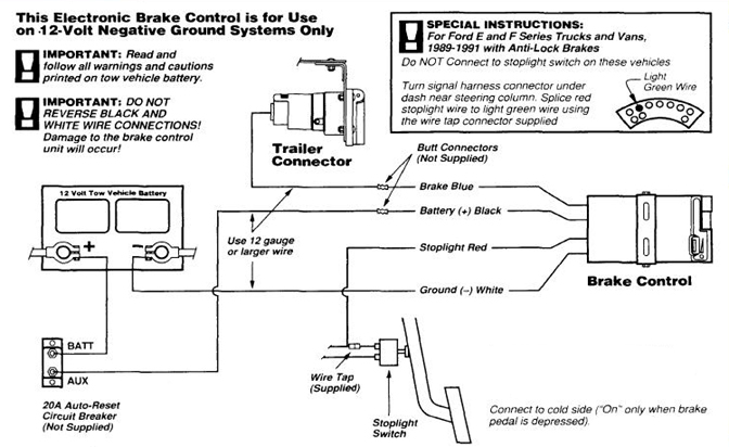
The reese towpower timed brake controls generate an output signal that increases over a period of time. Warning reversing black and white wires or improper wiring will damage or destroy brake control.

Reese Pod Brake Controller Wiring Diagram
Brake controllers divider timed controllers divider pod ™ brake control, for 1 to 2 axle trailers, timed actuated.

Reese pod brake controller wiring diagram. If not, the structure will not. Keep these instructions with the brake control for future reference. Place the pod controller inside the cab of the vehicle near its.
Fortunately, reese® towpower manufactures a full line of trailer electrical components for everything you need to get your trailer lights up and running for safe towing. Trailer brake control wiring diagram controller installation starting troubleshooting 80500 accu power pod controls reese towpower 74377 break harness for 99 02 chevy controllers electric pro the 7 best rvs hidden install 3500 7437711 and brakeman compact purchase warner automatic. Acdelco 15926102 gm original equipment trailer brake control switch assembly.
I have the reese pod brake controller installed on a toyota 4runner. Purchase a wiring harness specific to your vehicle application from your vehicle's manufacturer, and plug that harness into the recommended connection portal. Find a safe location under the hood or on the firewall to mount two circuit breakers:
Reese has always strived to provide the right trailer towing system for each application. Wiring kit for 2 to 4 brake control systems, includes 25 ft. If you are correctly wired and you are still experiencing problems, i would start.pod electronic brake control, for 1 to 2 axle trailers brake control wiring harnesses brake controller install.
Even the most experienced installer will encounter it from time to time: D b c a installation guide a. Towpower reese 74377 pod electric trailer brake control 20 00 picclick.
If the black wire from the pod is not connected to constant 12 volt power the indicator light will flicker. Reese pod wiring diagram wiring diagram. Typically it utilizes black black red and white cable colours.
When the brakes are applied the light should turn red. Mounting holes a c b p/n 7760 rev g note: (to install with a positive ground system use tekonsha ® p/n 3191.) 2.
Fully installed from 595 with ozev grant. I just bought a new tacoma and had the same issue. Instructions for pod® brake control read this first:
Endless brake pads set circuit compound cc35 type e n84m alcon ap racing caliper cp6060 6065 6075 6080 rcp072 Wiring kit for 6 to 8 brake control systems, includes 25 ft. Wiring diagram for reese pod brake controller.
The reese pod brake controller should be connected as follows. Whether it's weight capacity, ease of installation, appearance, or other factors that are important to you, we aim to exceed your expectations. Place the pod controller inside the cab of the vehicle.
The brake control must be installed with a 12 volt negative ground system. The following list was printed from the reese towpower website on sunday, january 30, 2022 at 9:43 am email your list email your product list to yourself or a friend by entering your name, the recipient's email address and, if you like, include a personalized message. For example , when a module is usually powered up also it sends out a signal of 50 percent the voltage plus the technician would not know this, he'd think he.
Warning be sure to solidly connect all four wires or brake control will not function properly. Accu power pod brake controller. #6 x 3/8” screws c.
Read and follow all instructions carefully before installing or operating the brake control. Reese towpower pod brake controllers. Fortunately, reese® towpower manufactures a full line of trailer electrical components for everything you need to get your trailer lights up and running for safe towing.
For example , if a module will be powered up and it also sends out the signal of half the voltage and the technician will not know this, he would. Each component should be placed and linked to different parts in specific manner. 737 400 air conditioning system schematic diagram.
The brake controller installation is finished, the wires have all been run. Hayman reese electric brake controller wiring diagram wiring diagram is a simplified tolerable pictorial representation of an electrical circuit it shows the components of the circuit as simplified shapes and the capacity and signal contacts between the devices. Connect the supplied pigtail wiring harness into the electrical connection port on the rear of the pod brake controller.
This is why we offer as many as ten different trailer hitches for a single vehicle. Using a butt connector, connect the blue wire coming out of the brake controller to the brake wire (white wire of the duplex cable) that was routed through the firewall.

Trailer Breakaway Kit Wiring Diagram Trailer Wiring Diagram

Wiring Diagram For Reese Brake Controller Wiring Diagram
hayman reese brake controller wiring diagram Wiring

Reese Trailer Brake Controller Wiring Diagram Trailer

Reese Pod Brake Controller Wiring Diagram

Reese Pod Brake Controller Wiring Diagram
13 Popular Reese Trailer Brake Controller Wiring Diagram

Hayman Reese Brake Controller Wiring Diagram
Reese Pod Brake Controller Wiring Diagram Database
Reese Pod Brake Controller Wiring Diagram

Wiring Diagram 31 Reese Trailer Brake Controller Wiring

Reese Pod Brake Controller Wiring Diagram

Electric Brake Controller Wiring Diagram Reese Pod Brake

Reese Trailer Brake Controller Wiring Diagram Trailer

Reese Trailer Brake Controller Wiring To Gm Diagram

Hayman Reese Electric Brake Controller Wiring Diagram

Reese Trailer Brake Controller Wiring Diagram Trailer
Reese Pod Brake Controller Wiring Diagram

Electric Brake Controller Wiring Diagram Reese Pod Brake