This should be standard usb pinout and wire colors, unless you have some very weird usb cable. If using a different usb sound card check the polarity with a meter as the usb plug may be the other way round.

PCM2702 USB Sound Card Circuit Electronic Circuit
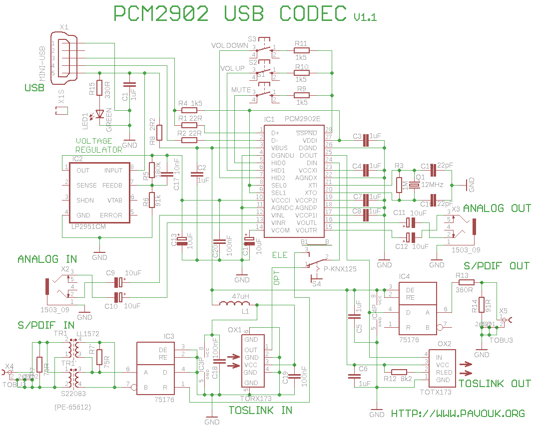
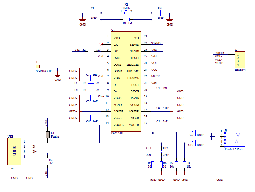
The vbus (usb bus power) pin and dgnd (digital ground) pins of the ic are connected to the +5v and ground pins of the usb respectively.

Usb sound card wiring diagram. The 12mhz crystal is connected between the xt0 and xt1 pins of the ic. First thing to do now is solder the usb cable to the sound card and make sure, that it still works. I gathered up parts to build a cable to connect a usb sound card to the 6 pin mini din socket on the rear of the radio.
Sometimes, the cables will cross. If the sound card is plugged in and receiving power, the red led on the sound card module will be illuminated. The integrated interface controller of pcm2702 is compliant to.
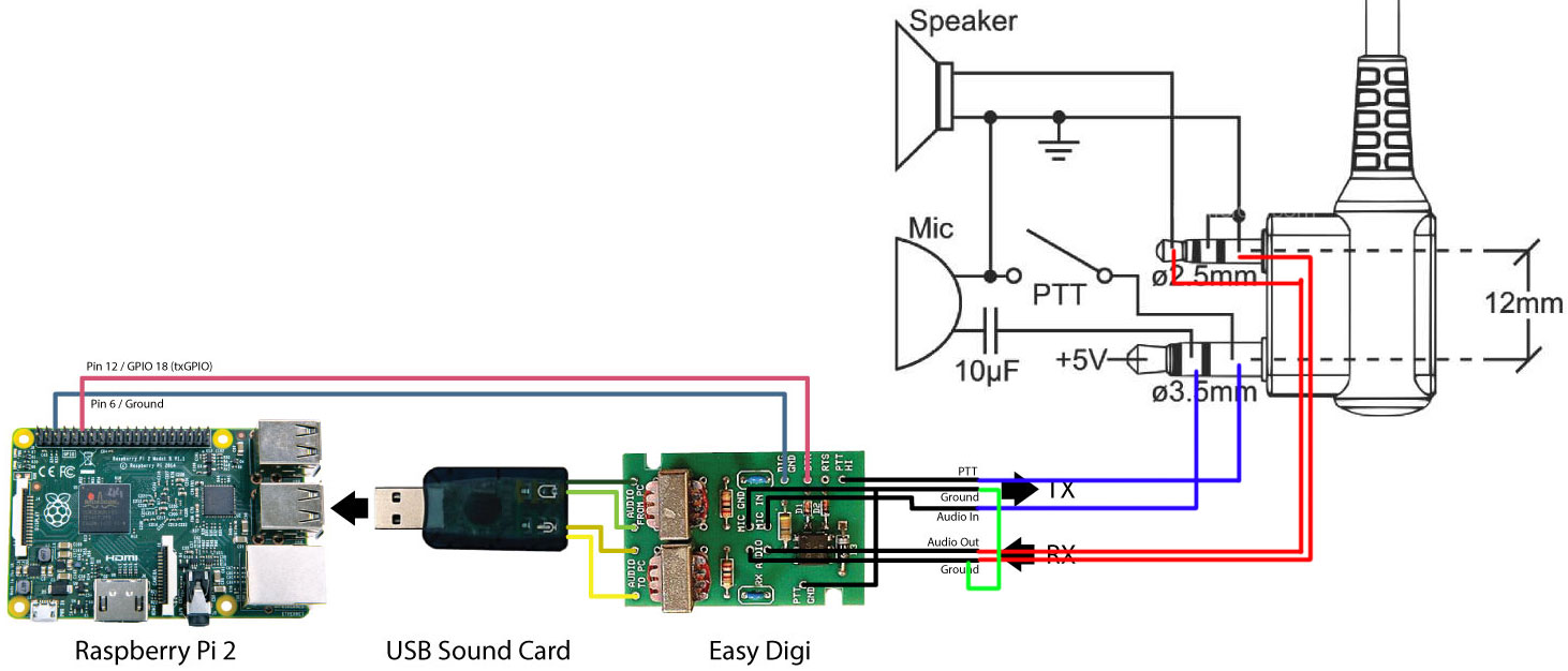
The wiring diagram i followed to solder the 3.5mm adapter cable takes a single trs connector and splits the in/output to two other trs connectors as shown below (attached). The next step is to be able to interface the rx and tx radios to the sbc. If the rig supports vox operation, via the selected audio port (vox is often not provided on auxilliary ports), only the usb audio interface is required as the tones, when present, will automatically key the radio.
Here you can have an idea of the ground wirings. Confirm the usb sound card has been selected. The process is actually super simple.
However, it does not mean link between the wires. For any given radio, there are likely to be a different jumper settings for. The usb module with its various connection points.
Front end turns pc sound card into high sd sampling oscilloscope analog devices. The positive rail is the lower one in the picture, and ground is the upper one. On my device the wires went from left to right:
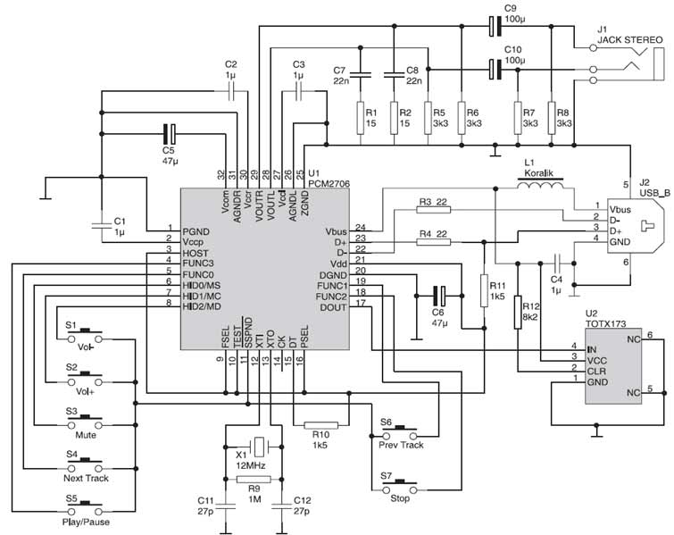
The pcm2702 is an integrated 16 bit digital to analog converter that has two digital to analog output channels. Also, to wire the whole audio circuit i followed exactly the scheme below (of course not considering the volume wheel, and wiring datas from the pi0 directly to the sound card). The signalink usb can be connected to any standard usb 1.1 or usb 2.0 jack on your computer.
Solder wires to a connector in a following order: Then only a single usb cable goes to the computer, and the computer powers the usb hub, rs232 adapter and the usb soundcard dongle, so no separate power supply is needed. You’ll need some soldering experience and a usb connector.
We are currently working on a hardware interface design, but in the meantime an easy digi and usb sound card should do the trick. Usb sound card with pcm2702 electronics lab com. Above is a basic diagram of how this should be wired.
Besides the usb mp3 module you get two 3.5mm female jack sockets, usb female cable or port, ir receiver and 5v regulated dc supply in the kit for this diy project. The supply rail is routed via a front panel switch. Also, use a scope or ac voltmeter to confirm receive audio path
[ ] communication program not working: The following schematic diagram shows the use of the usb audio interface and the usb serial interface described below. The card has analog input and output, an electrical s / pdif output, galvanically separated input and optical input and output toslink.
Injunction of 2 wires is usually indicated by black dot at the intersection of two lines. The decoded audio signals at the voutl and voutr pins of the ic. Pcm2706 usb sound card electronic schematic diagram.
All communications programs and other Usb sound card raspberry pi projects. Before attaching the usb cable, your computer should be turned on, and windows (or another supported operating system) should be running.
We have provided a standard usb cable for this purpose. So leveraging what i had learned in my earlier posting on usb sound cards. Cut off the original connector and strip the wires.
This is usb sound card with pcm2902 chip. Make a sound card with pcm2704. If it is not illuminated, check usb connection at the computer.
According to earlier, the traces in a micro usb to hdmi wiring diagram signifies wires. The supply lines are the outer two of the four connectors on the usb plug. It has become the standard connection method for wide variety of devices.
The heart of usb sound card is pcm2902 it is a circuit connection, which is a complete usb codec. Designing and building a usb sound card is no longer a head ache because we have got the pcm 2702 integrated circuit from texas instruments. This versatile module features usb player, sd card player, fm player and an auxiliary input.
For the purpose of testing the d / a converters, i built a simple usb sound card with the circuit pcm2902. The wiring is very simple with only three wires, audio in, audio out and a. Build this simple but amazing usb audio interface for only 5.
Some diagrams will show you different order with middle (data) wires switched, but that won’t work. The weak link here is the usb sound card.

Usb Micro Sd Card Reader Circuit Diagram Wiring Diagram

Usb Micro Sd Card Reader Circuit Diagram Wiring Diagram

Optically Isolated Usb Hub Wiring Diagram USB Wiring Diagram
My World My Rules USB Sound Card Circuit

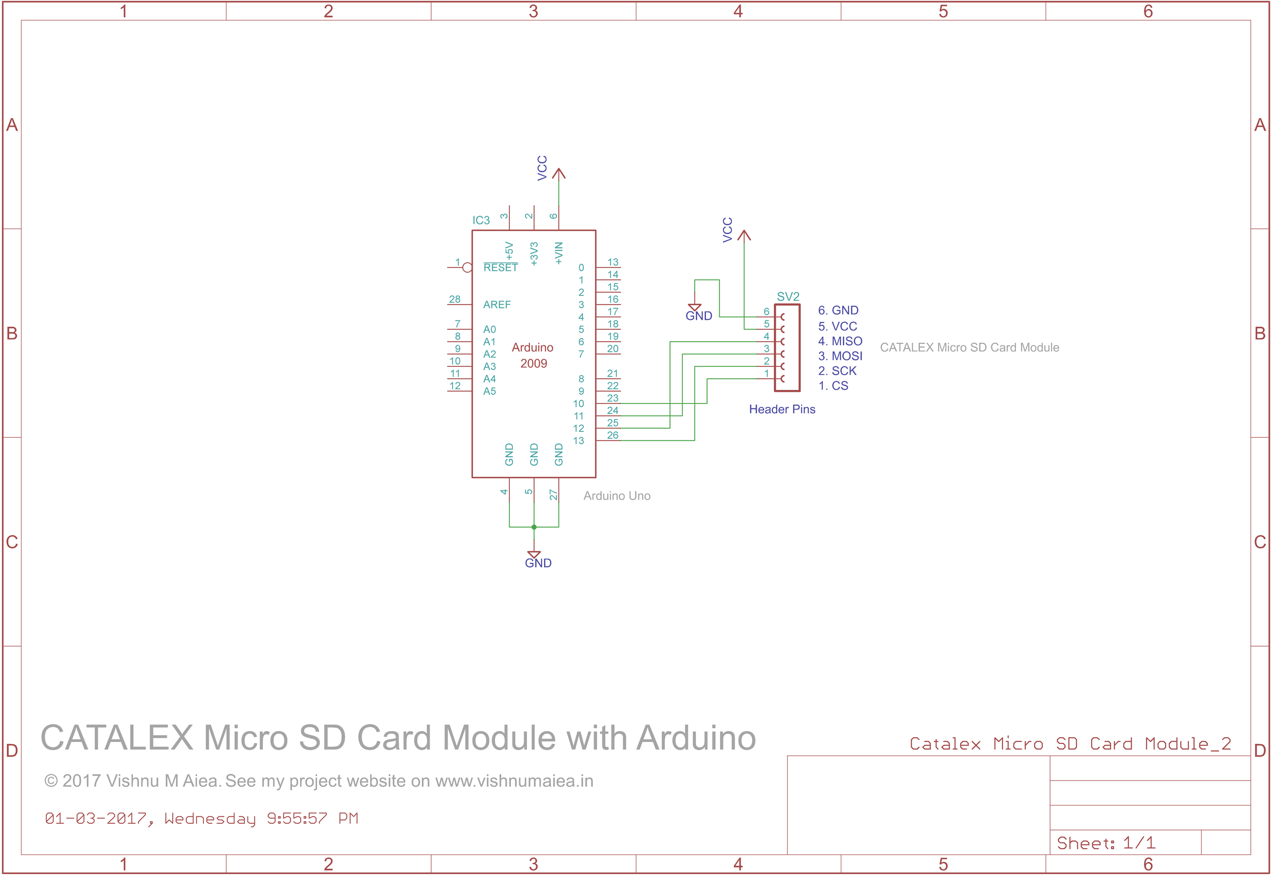
Usb Micro Sd Card Reader Circuit Diagram Wiring Diagram
Usb Control Board Wiring Diagram Complete Wiring Schemas

USB Sound Card with PCM2702 PCM2702

Simple Oscilloscope Schematic Wiring Diagram
> circuits > USB Sound Card with PCM2902 l25741 Next.gr

Simple Oscilloscope Schematic Wiring Diagram
Help setting up USB Sound with vox App_rptusers
Simple Oscilloscope Schematic Wiring Diagram
PCM2902 Soundcard with Microphone Input Schematic under
Sound Card with PCM2704
PCM2706 High Fidelity USB Soundcard / USB Headphones

Telephone Socket Wiring Diagram The Wiring
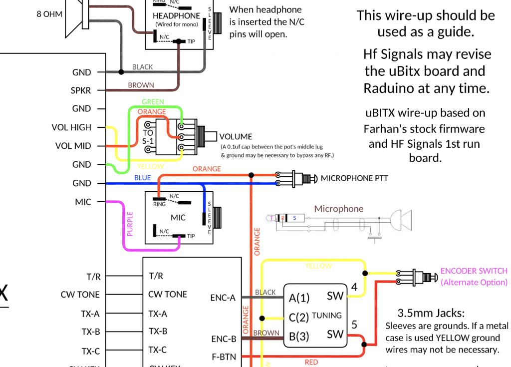
Ubitx Wiring Diagram

Telephone Socket Wiring Diagram The Wiring
Soundcard Interface