How to make inverter 12v dc to 220v ac making circuit diagram making transformer electr circuit diagram electrical circuit diagram electronics mini projects. The first element is emblem that indicate electrical element from the circuit.
![]()
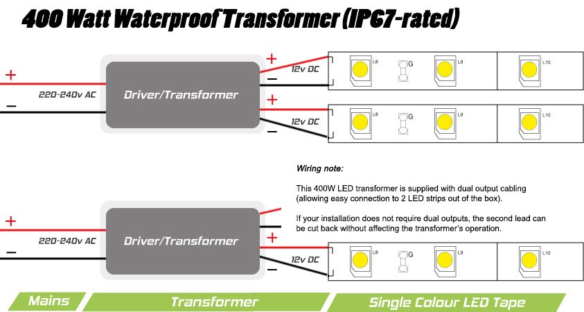
24V 400 Watt IP67 Transformer for InStyle LED Tape
3 phase 240v motor wiring diagram.

240v to 12v transformer wiring diagram. The other two wires left will be the two ac voltages, in the case of a 12v transformer, it will be two 12v connections. Show activity on this post. On wiring diagram for 240v led downlights.
There are two things which are going to be found in any 480v to 240v transformer wiring diagram. Thus the center tap is common ) volts to either of the blue wires. The first element is emblem that indicate electrical element from the circuit.
My thinking is to get it all installed and wired up, then get a qualified competent and. Collection of step down transformer 480v to 120v wiring diagram. There are the output terminals of the transformer, the voltage across it will be 24v ac.
This is the centre tapped wire of the transformer; 480v 3 phase transformer wiring diagram step down tags to 120v. To get this wiring arrangement, you need to connect the yellow and blue wires together.
General acme® transformer™ wiring diagrams primary: Ok, the transformer has a 24 volt secondary. They also have to be connected in proper phase.
This is the centre tapped wire of the transformer. It is intended to help all the average consumer in developing a suitable system. Inverter 12v dc to 240v electronic schematic diagram.
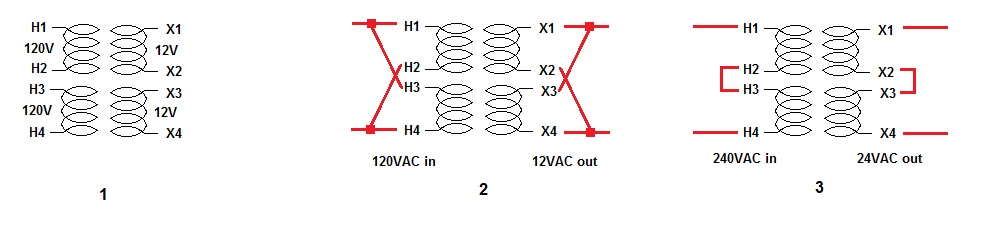
This wire can be combined with either t1 or t3 to get 12v ac across it. This sounds like a transformer with dual input and output windings so that the input can be either 120v or 240v, and the output can be either 12v or 24v. To properly read a wiring diagram, one offers to know how the particular components inside the method operate.
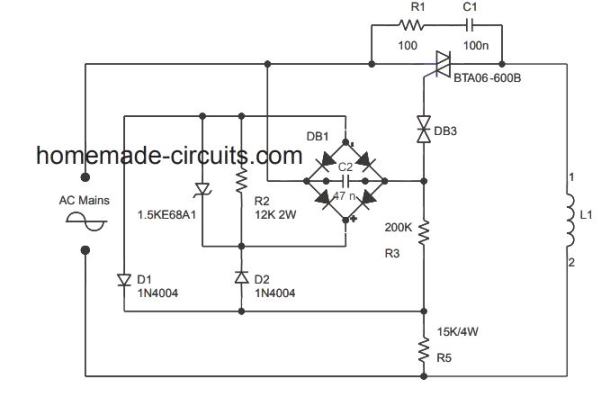
It is intended to help all the average consumer in developing a suitable system. Wiring diagram 240v led downlights.downlights are wired in a radial circuit and so the feed wire goes to the first light in the circuit and then from the first to. After this you will get a 30v pulsulating ac voltage.
A circuit is generally composed by many components. If you have any questions regarding these wiring diagrams or are having any difficulty correctly installing our transformers, please contact hps customer service or technical support in the u.s. These guidelines will probably be easy to comprehend and apply.
A circuit is generally composed by various components. One set for primary, one set for secondary. Wiring diagram comes with several easy to follow wiring diagram directions.
That is 24 volts between the two blue wires of the secondary. This will effectively be the ground in most circuit applications. The other thing you will find a circuit diagram could be traces.
Each component should be placed and connected with different parts in particular manner. Unscrew the cover and you'll see 2 sets of connectors/terminals. Connect 230v to terminals marked as primary (at the top of the picture), and the second set of.
For v v v or v units. This transformer sits comfortably behind my generator's starting battery. 240 to 24 volt transformer wiring diagram collection.
October 2007 rev4 page 1 of 9 None x4x1 h4 h3h2 h1 x2 x3 primary. This circuit designed using the combination of main components ic cd4047 transistor tip122 and 2n3055.
This will give you the centre tap, or 0v as it gives. Ta series 230v 230vac primary voltage. This will be 208v 240v 480v 575v or 600v.
/ 12, 2 /2% anfc, 4, 2 1/2% bnfc x4 x1 h10 h2 h3 h1 x2 x3 h5 h6 h4 h7 h8. 480v to 120v transformer wiring. It was designed for 100% duty cycle at a 23a @240v current rating and it will handle 100% imbalanced loads (up to the max of 23a per 120v leg.) we've been using this transformer with our onan 5500w for almost 2 years without issue.
Another thing that you will locate a circuit diagram could be traces. If this is the case then the connections have to be in parallel for 120v input and 12v output, or in series for 240v input and 24v output. Transformer wiring diagram 480 to 240.
For instance , when a module will be powered up and it also sends out a new signal of 50 percent the voltage and the technician does not know this, he would think he offers a challenge, as this individual would expect a 12v signal. The first component is emblem that indicate electrical component from the circuit. This wire can be combined with either t1 or t3 to get 12v ac across it.
27.12.2018 · there are two things which are going to be found in any 480v to 240v transformer wiring diagram. Hps imperator tm industrial control transformer wiring diagrams issue date: Install 3 or 4 x v 3w led downlights in all rooms.
The following diagram shows the australian plug wiring configuration. We offer advice on wiring downlights and other lights at dusk lighting. A wiring diagram is a schematic type that uses abstract illustrated symbols to show all of the components of a system.
However, the secondary also has a ct (center tap) so between either blue wire and the yellow (ct) you will measure 12 volts. However the secondary also has a ct center tap so between either blue wire and the yellow ct you will measure 12 volts. These are the input wires for the transformer, it is connected to the phase and neutral of ac mains.
Unit supports 50hz or 60 hz as required single phase chart requires 1 transformer low voltage lv high voltage. There are two things that will be found in any 24 volt transformer wiring diagram. Can't make it much simpler if using one transformer per downlight, wiring is exactly the same as if the downlights were mains.
None x4x1 h4 h3h2 h1 x2 x3 primary:
Wiring Manual PDF 120v Transformer Wiring Diagram

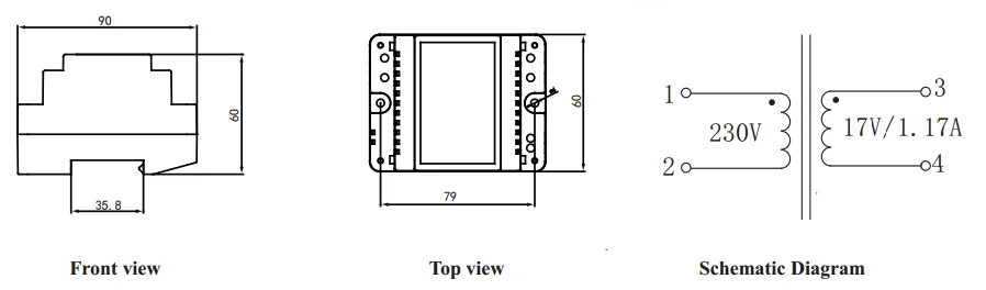
240v Ac 24v Dc Encapsulated Transformer Buy 240v Ac 24v

240v 24v Transformer Wiring Diagram schematic and wiring
![]()
480V To 120V Transformer Wiring Diagram Wiring Diagram

240v To 12v Transformer Wiring Diagram Wiringpedia

AC 240v to DC 12v converter electrical diagram YouTube
![]()
12v Transformer Wiring Diagram
110 Volt Circuit Diagram DHNX Wiring Diagram
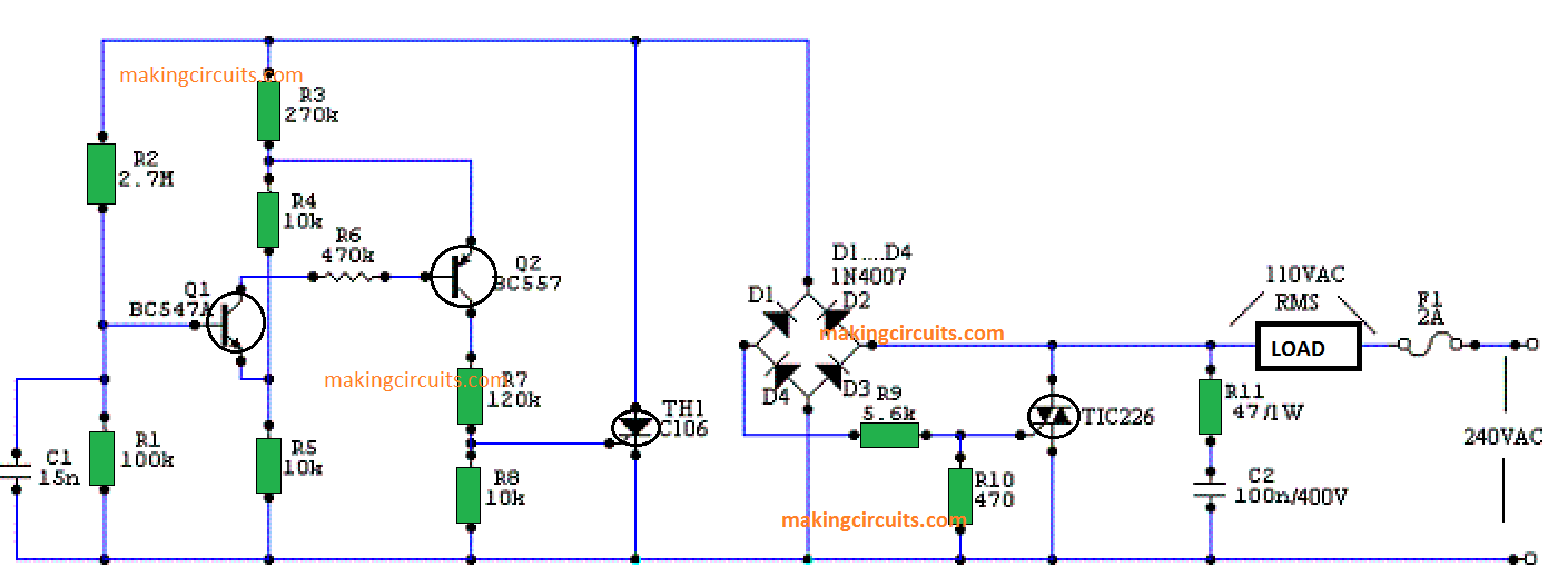
110 Volt Circuit Diagram DHNX Wiring Diagram
![]()
208 To 24 Volt Transformer Wiring Diagram Wiring View

Inverter 12V DC to 240V DC Schematic Design
12v Transformer Wiring Diagram
Dc Transformer Wiring schematic and wiring diagram


24V Transformer Wiring Diagram Xs 4469 Wiring Diagram
Dual voltage transformer.jpg
![]()
24v Transformer Wiring Diagram 34
Scematic Diagram 12v To 240v Circuit
480v To 240v Transformer Wiring Diagram MORPHINEANDDRUGS
110 To 12 Volt Converter sim 4000w step up down 110v 220
